Detacher system and method having an RFID antenna for a combination eas and RFID tag

a technology of rfid antenna and combination eas, which is applied in the field of eas tags, can solve the problems of ineffective magnetic type detachable units, wire antennas that are too long to fit inside the detachable unit housing, and retail stores already pay a considerable amount for re-usable hard tags

Active Publication Date: 2009-09-10
SENSORMATIC ELECTRONICS CORP
View PDF10 Cites 35 Cited by
  • Summary
  • Abstract
  • Description
  • Claims
  • Application Information

AI Technical Summary

Problems solved by technology

Retail stores already pay a considerable amount for hard tags that are re-useable.
However, these magnetic type detaching units are ineffective with mechanical spring clamp type mechanisms used with combination hard tags.
The problem with this approach is that the wire antenna is too long to...

Method used


Image

  • Detacher system and method having an RFID antenna for a combination eas and RFID tag
  • Detacher system and method having an RFID antenna for a combination eas and RFID tag
  • Detacher system and method having an RFID antenna for a combination eas and RFID tag

Examples


Embodiment Construction

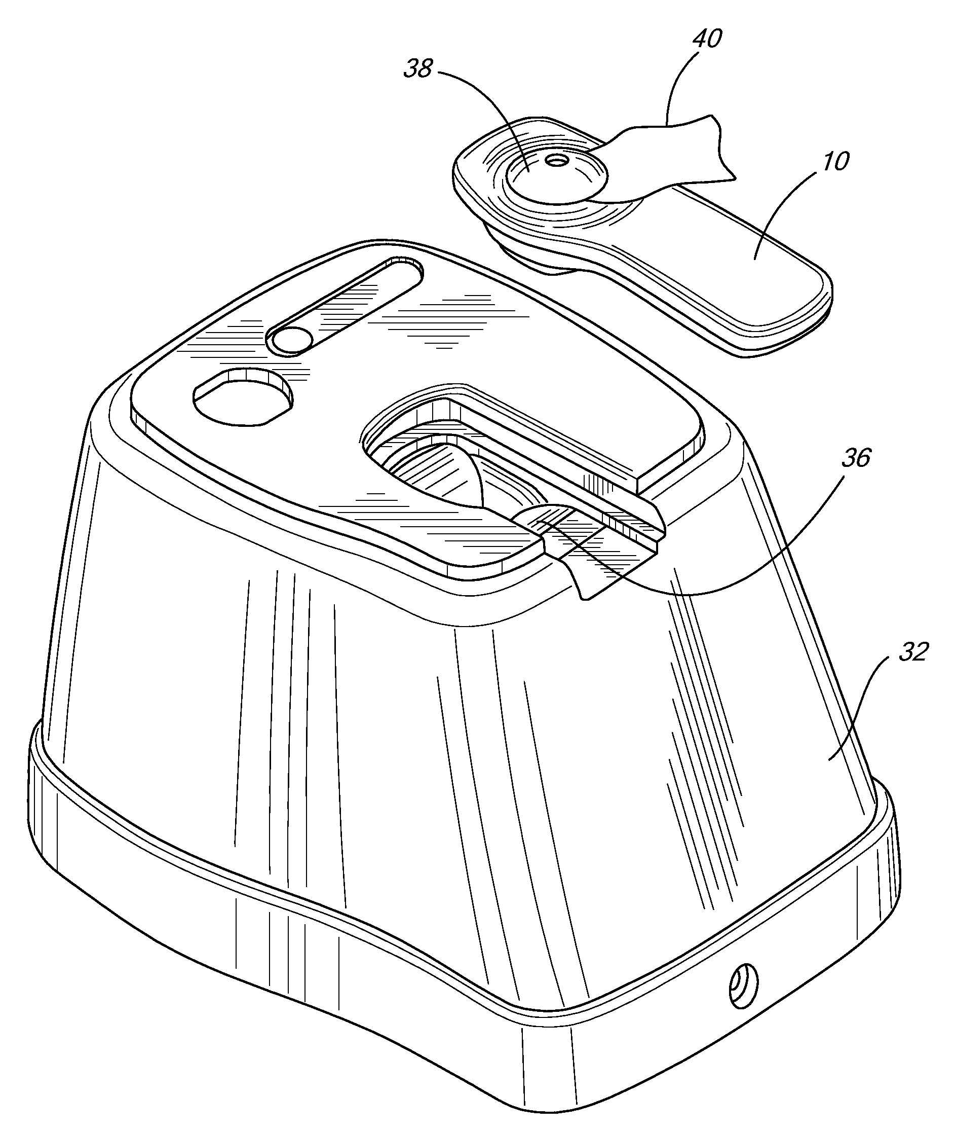
[0023]The present invention is directed toward a non-magnetic detacher unit for combination EAS / RFID tags. The invention consists of a detacher unit equipped with a mechanism which can release the spring clamp of a combination EAS / RFID tag when the clamp is placed in a particular region of the detacher. When the combination EAS / RFID tag is placed in a certain region proximate the detacher unit, the RFID information is read from the tag by a near field antenna and RFID reader allowing the spring clamp attachment mechanism in the combination tag to be removed.

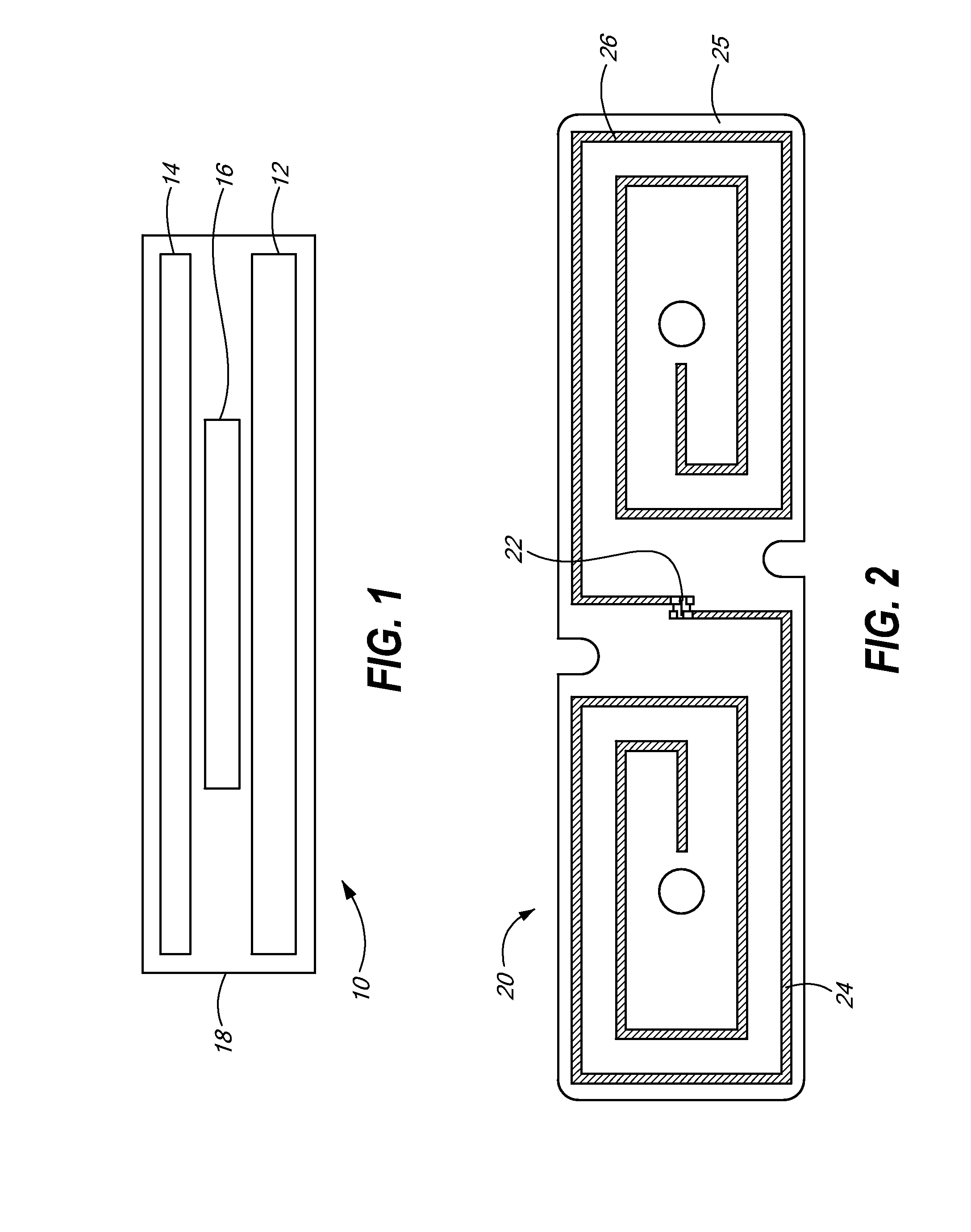
[0024]Referring now to the drawing figures in which like reference designators refer to like elements, there is shown in FIG. 1 a diagram of an exemplary EAS / RFID tag used with the detaching unit of the present invention. FIG. 1 shows a combination EAS / RFID tag 10, which includes an electronic article surveillance (EAS) element 12, an RFID element 14, one or more spacing elements 16, where EAS element 12, RFID element 14 and one ...


PUM


Abstract

A detacher unit for disengaging a combination EAS/RFID tag from its article. The detaching unit detaches the spring clamp mechanism of a combination EAS/RFID tag when the tag is placed within a particular region within the detaching unit. A near field magnetic loop antenna is situated within the placement region in a housing. When the combination EAS/RFID tag is placed within the placement region just above the near field magnetic loop antenna, the RFID code of the tag is read and the detachment unit releases the clamp mechanism that attaches the EAS/RFID tag to its article.

Description

CROSS-REFERENCE TO RELATED APPLICATION[0001]n / aSTATEMENT REGARDING FEDERALLY SPONSORED RESEARCH OR DEVELOPMENT[0002]n / aFIELD OF THE INVENTION[0003]The present invention relates to EAS tags and specifically, to a method and system for detaching a spring clamp mechanism on a combination EAS / RFID tag.BACKGROUND OF THE INVENTION[0004]Electronic article surveillance (“EAS”) systems are generally known in the art for the prevention or deterrence of unauthorized removal of articles from a controlled area. In a typical EAS system, EAS tags, markers and labels (collectively “tags”) are designed to interact with an electromagnetic field located at the exits of the controlled area, such as a retail store. These EAS tags are attached to the articles to be protected. If an EAS tag is brought into the electromagnetic field or “detection zone,” the presence of the tag is detected and appropriate action is taken, such as generating an alarm. For authorized removal of the article, the EAS tag can be...

Claims


Application Information

Patent Timeline
IPC IPC(8): G08B13/14
CPCE05B73/0017E05B73/0052E05B73/0064G08B13/2448G07G1/009G08B13/2417G06Q20/3278
Inventor COPELAND, RICHARD L.
Owner SENSORMATIC ELECTRONICS CORP
Why Eureka
Try Eureka