
Wristwatch

a wristwatch and wristwatch technology, applied in the field of wristwatches, can solve the problems of inconvenient wristwatch wear and not always very comfortable for wear, and achieve the effect of reducing the rigid part of the wristwatch and improving comfor

Inactive Publication Date: 2009-09-10
LEPINE JEAN PIERRE
View PDF13 Cites 5 Cited by
  • Summary
  • Abstract
  • Description
  • Claims
  • Application Information

AI Technical Summary

Benefits of technology

[0004]Thus, the technical problem resolved by the primary object of the present invention is to offer a watch bracelet including a main case section and a removable bracelet, each bracelet end being connected at its free ends, respectively, to two connection elements connected to the main, the watch bracelet avoiding problems of the state of the current art and being able to adapt better to the body contour of the wearer, while offering improved use comfort.
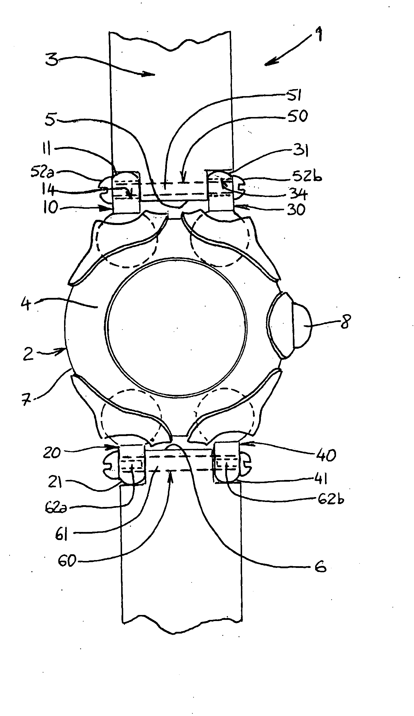
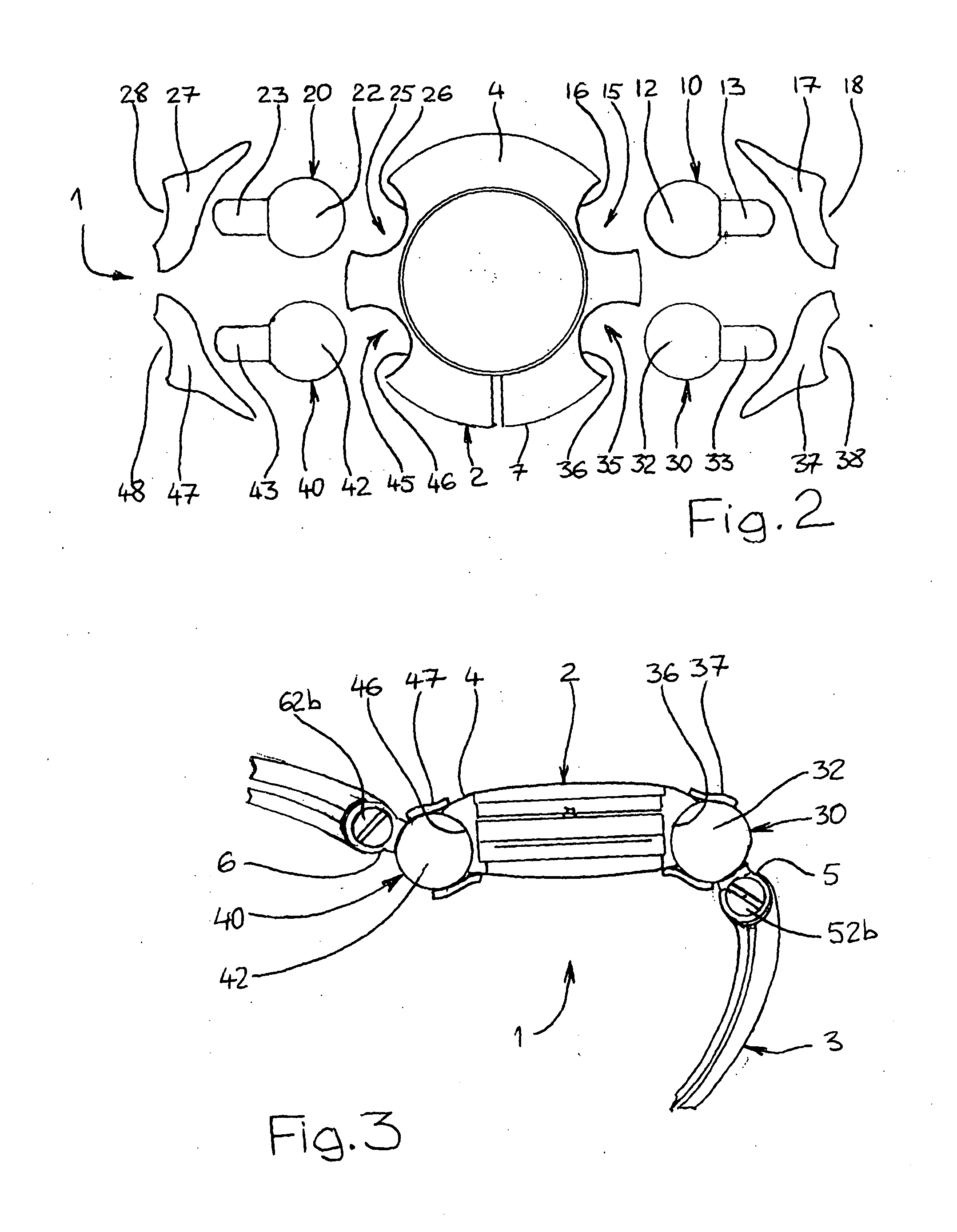
[0006]The invention thus defines an advantage in reducing the dimensions of the rigid part of the watch bracelet. In effect, the overhanging connection elements are not connected in a rigid manner to the watch case main section. Due to their relative mobility, each connection element is naturally oriented and follows a reasonable tangential direction to the curve of the wearer's wrist. The set formed by the main and the connection elements therefore provide a structure that is sufficiently flexible to accommodate in a superior manner the wearer's wrist, and improves comfort substantially.

Problems solved by technology

This type of watch bracelet is inconvenient and not always very comfortable to the wearer since it presents a part having dimensions that are relatively important, these being rigid structures that do not permit the watch bracelet to easily adapt to the size of a wearer's wrist.

Method used


Image

  • Wristwatch
  • Wristwatch
  • Wristwatch

Examples


Embodiment Construction

[0014]For reasons of clarity, the same numbered elements are designated by identical reference numbers in all of the views. Further, only the essential elements, necessary for an understanding of the invention have been shown without respect for actual scale and in a schematic manner.

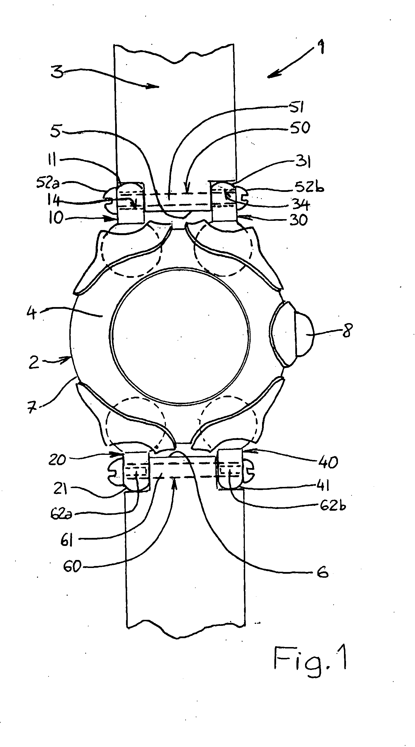
[0015]FIG. 1 illustrates a watch bracelet 1 that essentially comprises a case 2 for a dial and a removable bracelet 3. In a classical manner, the case 2 includes a main section 4, hereinafter referred to as the main 4, the latter housing a watch movement that is not illustrated in the figures for purposes of clarity. The ends 5, 6 of the bracelet 3 are removably connected to the main 4 by an intermediary structure, notably two pairs of connection elements 10, 30; 20, 40 that are respectively disposed in opposition on the boundary 7 of the main 4. It is also noticed that a crown 8 is present.

[0016]Conforming to the object of the present invention, each connection element 10, 20, 30, 40 is movably mounted...


PUM


Abstract

A wrist watch includes a watch case main and a removable strap. Each end of the strap is solidly connected to respective free ends of two linking elements that are solidly connected to the main. Each linking element is mounted so that it can move in relation to the main and the free end of each linking element can be oriented in different directions.

Description

FIELD OF THE INVENTION[0001]The present invention relates to a watch bracelet designed to be worn on a wearer's wrist.BACKGROUND OF THE INVENTION[0002]As its name indicates, a watch bracelet is a watch mounted on a bracelet that can be made, for example, in leather, in metal, or in plastic. Such a watch bracelet is essentially made of a watch case containing a watch movement as well as a detachable bracelet for which the ends are fixed in a removable manner to the central portion of the watch case, hereinafter referred to as a middle. The case is generally equipped with two pairs of lugs forming connection elements that are respectively connected at two opposing sides to the watch case middle, and which extends in the same direction but in opposite senses. The free end of each lug generally includes a bore designed to receive the end of a telescoping pin generally referred to as a push pin, that is itself connected to the bracelet ends.[0003]This type of watch bracelet is inconvenie...

Claims


Application Information

Patent Timeline
IPC IPC(8): G04B37/14
CPCG04B37/1486
Inventor LEPINE, JEAN-PIERRE
Owner LEPINE JEAN PIERRE
Learn More