Connecting Cannulated Bone Screws

a technology of cannulae and bone screws, applied in the field of orthopaedic surgery, can solve the problems of lag screw dependent, ineffective against fracture, and limitation of this techniqu

Inactive Publication Date: 2009-09-10
PARK SANGDO
View PDF4 Cites 61 Cited by
  • Summary
  • Abstract
  • Description
  • Claims
  • Application Information

AI Technical Summary

Benefits of technology

[0006]This method of bone fracture fixation seeks to provide a rigid construct which is effective and offers a means to circumvent the limitations of the commonly used lag screw by utilizing engagement of internal threads on an implantable object associated with the bone at one side of the fracture with the external threads on the shaft of another implantable object associated with the bone at the opposite side of the fracture. The preferred embodiment comprises two cannulated screws of different diameters which associate with the bones at the opposite sides of the fracture via their screw heads contacting the bone surfaces, and the screws are screwed into the bones manually or drilled towards each other and engage by means of internal threads of the larger-diameter cannulated screw and the external threads of the smaller-diameter cannulated screw. The engagement of the two cannulated screws is aided by a guiding mechanism involving a guide pin which guides the trajectory of both screws into the bones and toward each other so that their threads may engage.

Problems solved by technology

However, there are some limitations to this technique.
One limitation is that the lag screw cannot cross more than one fracture line and thus is ineffective against fractures with fracture lines that run roughly parallel.
And another limitation is that the lag screw is dependent on the quality of screw thread purchase on the bone at the far side of the fracture.
Poor bone quality means poor fixation.
Thus in these two instances, a more invasive and time-consuming option such as plate fixation is used.

Method used


Image

  • Connecting Cannulated Bone Screws
  • Connecting Cannulated Bone Screws
  • Connecting Cannulated Bone Screws

Examples


Embodiment Construction

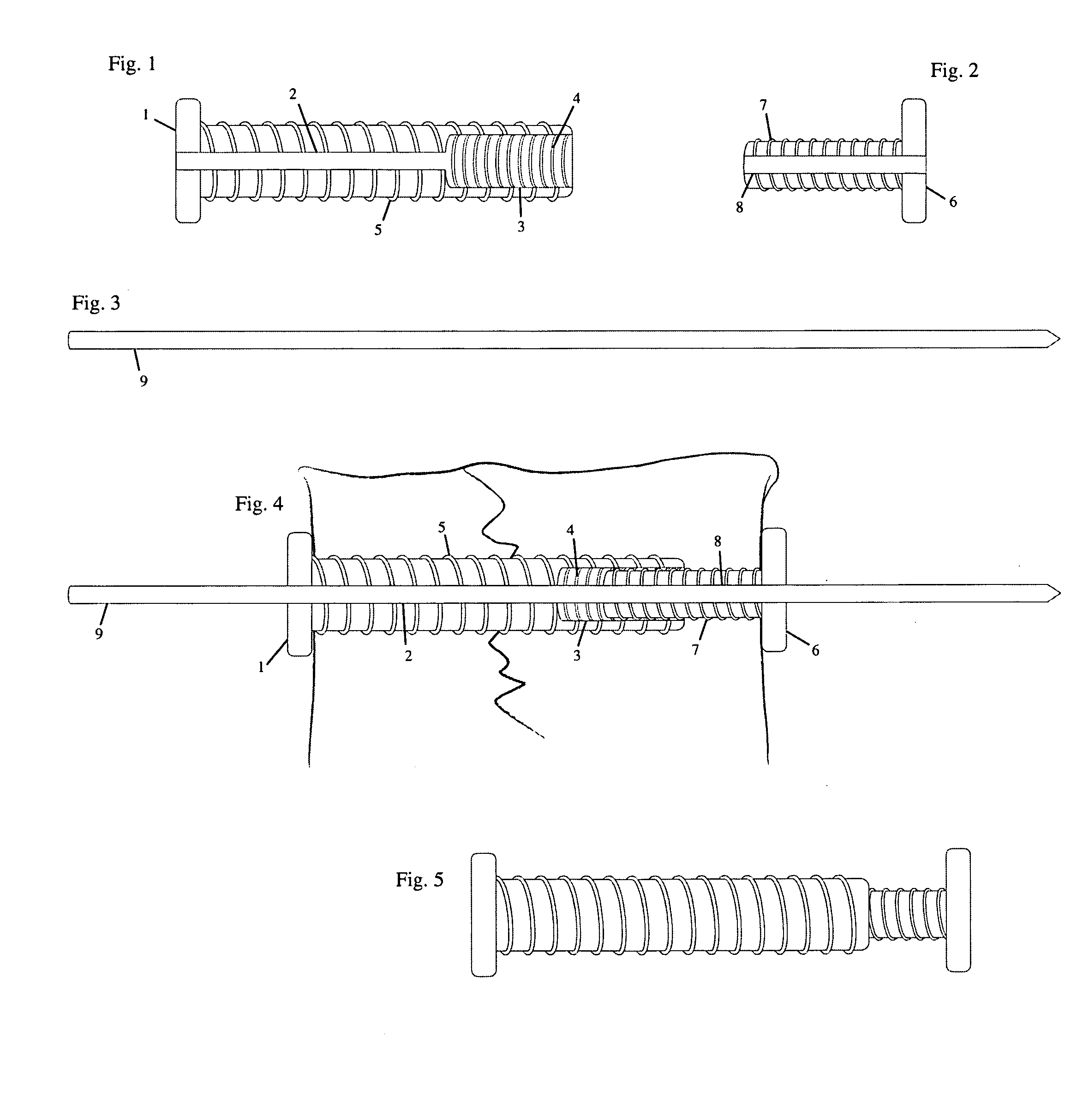
[0018]FIG. 1 is a cross-sectional view of the larger-diameter cannulated screw with internal threads 4 demonstrating head 1, centrally located proximal bore 2, and the larger distal bore 3 which is in continuity with the proximal bore 2. The larger-diameter cannulated screw may possess external threads 5 along the entire length of the screw shaft as demonstrated in FIG. 1 or partially along the length of the screw shaft.

[0019]FIG. 2 is a cross-sectional view of the smaller-diameter cannulated screw with external threads 7 demonstrating head 6 and a centrally located bore 8. The smaller-diameter cannulated screw is sized so that the external threads 7 thread onto and engage the internal internal threads 4 of the larger-diameter cannulated screw. The diameter of bore 8 of the smaller-diameter cannulated screw is equal to the diameter of proximal bore 2 of the larger cannulated screw. The external threads 7 of the smaller-diameter cannulated screw may be present along the entire length...


PUM


Abstract

A method of bone fixation comprises engagement of internal threads on an implantable object associated with the bone at one side of the fracture with the external threads on the shaft of another implantable object associated with the bone at the opposite side of the fracture. The preferred embodiment comprises two cannulated screws of different diameters which associate with the bones at the opposite sides of the fracture via their screw heads contacting the bone surfaces, and the screws are screwed into the bones manually or drilled towards each other and engage by means of internal threads of the larger-diameter cannulated screw and the external threads of the smaller-diameter cannulated screw. The engagement of the two cannulated screws is aided by a guiding mechanism.

Description

BACKGROUND OF THE INVENTION[0001]1. Technical Field[0002]This method of bone fracture fixation is of relevance to the field of orthopaedic surgery.[0003]2. Description of the Prior Art[0004]There are several ways to achieve bone fracture fixation in orthopaedic surgery. The simplest is the use of a lag screw. It consists of a head and a shaft which is partially threaded only distally while the proximal portion of the shaft immediately adjacent to the head is smooth. It works by engaging the threaded portion of the shaft into the bone at the far side of the fracture and compressing this against the bone at the near side of the fracture using the head of the screw. However, there are some limitations to this technique. One limitation is that the lag screw cannot cross more than one fracture line and thus is ineffective against fractures with fracture lines that run roughly parallel. And another limitation is that the lag screw is dependent on the quality of screw thread purchase on th...

Claims


Application Information

Patent Timeline
Patent Type & Authority Applications(United States)
IPC IPC(8): A61B17/56
CPCA61B17/683A61B17/8897A61B17/864
Inventor PARK, SANGDO
Owner PARK SANGDO
Why Eureka
Try Eureka