Fuel reformer housing container and fuel reforming apparatus

a technology of fuel reformer and housing container, which is applied in the direction of domestic cooling apparatus, combustible gas production, semiconductor/solid-state device details, etc., can solve the problems of fuel cell system complexity, small power generation loss, and temperature rise of fuel reformer housing container, so as to maintain a level of vacuum and less power generation loss

Inactive Publication Date: 2009-09-17
KYOCERA CORP
View PDF12 Cites 10 Cited by
  • Summary
  • Abstract
  • Description
  • Claims
  • Application Information

AI Technical Summary

Benefits of technology

[0016]The invention has been completed in consideration of the above-stated problems in the related art, and an object of the invention is to provide a fuel reformer housing c

Problems solved by technology

However, the conventional outer wall of the fuel reformer housing container formed into the double-layered structure is not adoptable in the fuel cell system for use in the mobile equipment because the fuel cell system becomes complicated and larger in size overall.
For the fuel cell system for use in the mobile equipment, there has been thus proposed a fuel cell system with a fuel reformer housing container composed of a base having a concave portion and a lid body, of which inner part is formed in a vacuum state to cut off the outward conduction of heat generated in reforming the fuel inside the fuel reformer, resulting in small power generation loss.
In this case, the level of vacuum inside the fuel reformer housing container drops,

Method used


Image

  • Fuel reformer housing container and fuel reforming apparatus
  • Fuel reformer housing container and fuel reforming apparatus
  • Fuel reformer housing container and fuel reforming apparatus

Examples


first embodiment

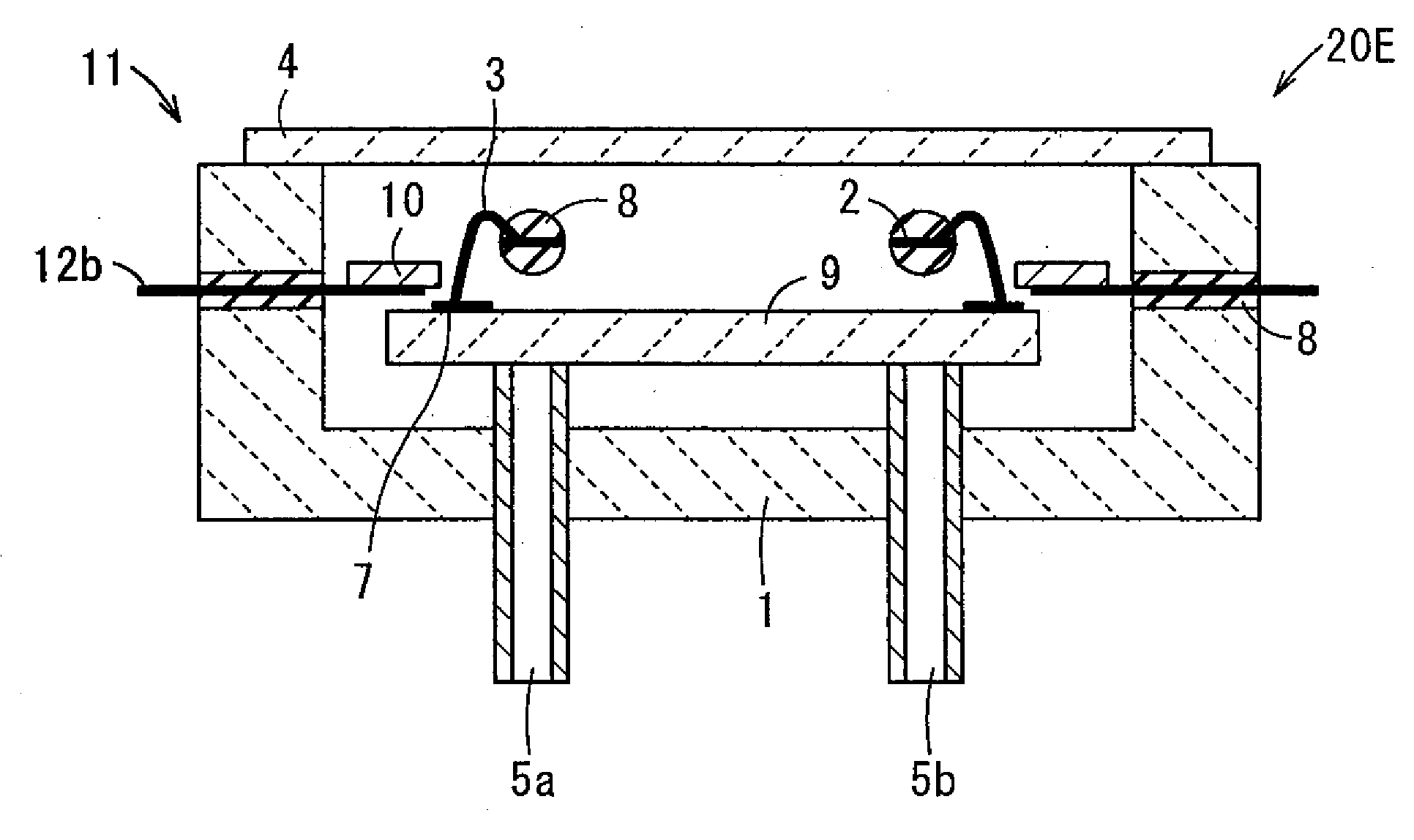
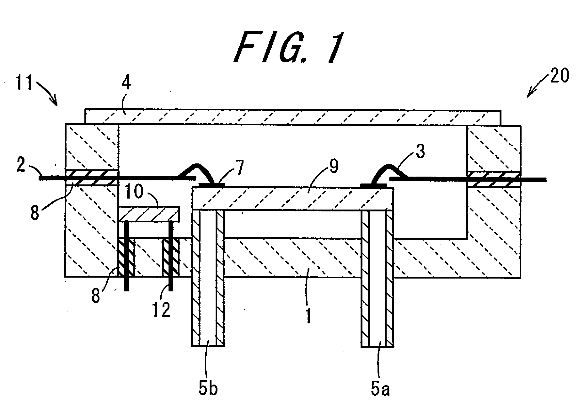
[0059]FIG. 1 is a sectional view showing a fuel reforming apparatus 20 according to the invention. The fuel reforming apparatus 20 includes a base 1, an external lead terminal 2 serving as a wiring for supplying electric power to a fuel reformer, a lid body 4, a supply pipe 5a serving as a supplying passage for supplying fuel, a discharge pipe 5b serving as a discharging passage for discharging reformed gas, an insulating sealing material 8, a fuel reformer 9, a gas adsorbent 10, and a lead terminal 12 on which the gas adsorbent 10 is fixed. The insulating sealing material 8 seals through-holes of the base 1, in which the external lead terminal 2 and the lead terminal 12 are fixed and insulated. A fuel reformer housing container 11 is configured so as to house the fuel reformer 9 by using the base 1, the lid body 4, the supply pipe 5a, and the discharge pipe 5b. In the fuel reformer housing container 11, the fuel reformer 9 and the gas adsorbent 10 are housed, and a concave portion ...

second embodiment

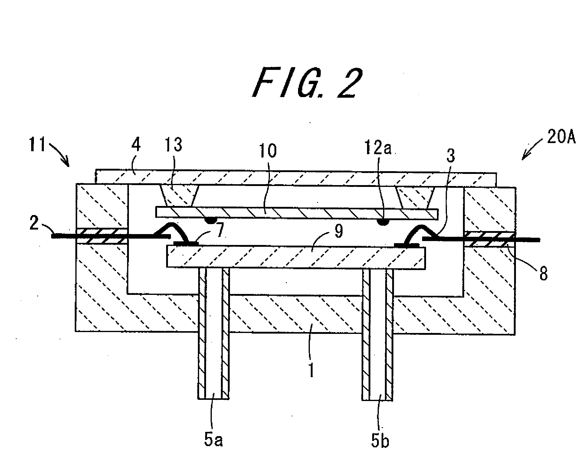
[0094]FIG. 2 is a sectional view showing a fuel reforming apparatus 20A according to the invention. In the present embodiment, parts corresponding to configuration according to the above-described embodiment will be denoted by the same reference numerals so that descriptions thereof will be omitted.

[0095]The fuel reforming apparatus 20A includes a base, an external lead terminal 2, a lid body 4, a supply pipe 5a, a discharge pipe 5b, an insulating sealing material 8, a fuel reformer 9 having an electrode 7, a gas adsorbent 10, and a lead terminal 12a. A fuel reformer housing container 11 is configured so as to house the fuel reformer 9 by using the base 1, the lid body 4, the supply pipe 5a, and the discharge pipe 5b. In the fuel reformer housing container 11, the fuel reformer 9 and the gas adsorbent 10 are housed, and a concave portion of the base 1 is hermetically sealed with the lid body 4, thus resulting in the fuel reforming apparatus 20A. The lead terminal 12a is configured i...

third embodiment

[0103]FIG. 3 is a sectional view showing a fuel reforming apparatus 20B according to the invention. In the present embodiment, parts corresponding to configurations according to the above-described embodiments will be denoted by the same reference numerals so that descriptions thereof will be omitted.

[0104]The fuel reforming apparatus 20B includes a base 1, an external lead terminal 2, a lid body 4, a supply pipe 5a, a discharge pipe 5b, an insulating sealing material 8, a fuel reformer 9 having an electrode 7, and a gas adsorbent 10. A fuel reformer housing container 11 is configured so as to house the fuel reformer 9 by using the base 1, the lid body 4, the supply pipe 5a, and the discharge pipe 5b. In the fuel reformer housing container 11, the fuel reformer 9 and the gas adsorbent 10 are housed, and a concave portion of the base 1 is hermetically sealed with the lid body 4, thus resulting in the fuel reforming apparatus 20B. In the present embodiment, it is notable that the adso...


PUM


Abstract

An object of the invention is to provide a fuel reformer housing container and a fuel reforming apparatus, which are capable of maintaining a level of vacuum inside the fuel reformer housing container favorably and which have less power generation loss. A fuel reformer housing container (11) includes a base (1) having a concave portion for housing a fuel reformer (9) in which reformed gas containing hydrogen gas is generated from fuel, a discharge pipe (5b) for communicating inside of the concave portion with outside thereof to discharge the reformed gas from the fuel reformer, a supply pipe (5a) for communicating inside of the concave portion with outside thereof to supply the fuel to the fuel reformer (9), and a gas adsorbent (10) housed in the concave portion, for adsorbing gas in the concave portion.

Description

TECHNICAL FIELD[0001]The present invention relates to a fuel reformer housing container for constituting a fuel reforming apparatus using a fuel reformer that generates hydrogen gas from a variety of fuels, for example, in a fuel cell system, and also relates to a fuel reforming apparatus.BACKGROUND ART[0002]In recent years, a fuel cell system has been in the limelight as a next-generation power source system that produces electric energy efficiently and cleanly, and in automobile market and in market of electric power co-generation system typified by a household fuel cell power generation system, field tests for practical implementation aiming at cost reduction have been already executed energetically.[0003]Besides, it has been examined recently to miniaturize the fuel cell system and use as a power source of mobile equipment such as a mobile phone, a PDA (Personal Digital Assistant), a notebook computer, a digital video camera and a digital still camera.[0004]Generally, in a fuel ...

Claims


Application Information

Patent Timeline
IPC IPC(8): C10J1/20F17B1/00
CPCB01J19/0093B01J2219/00824B01J2219/00835B01J2219/00873B01J2219/00921Y02E60/50C01B2203/042C01B2203/066H01M8/0612H01M8/2475C01B3/32
Inventor BASHO, YOSHIHIROHASHIMOTO, TOSHIHIROMIYAHARA, MASAAKIMORI, RYUJI
Owner KYOCERA CORP
Why Eureka
Try Eureka