Spark timing and control during transitions between spark ignited combustion and homogenous charge compression ignition

a technology of spark ignition and ignition timing, applied in the direction of electrical control, process and machine control, instruments, etc., can solve the problems of inconvenient control of the ignition process, inability to achieve uniform transitions between si and hcci modes, and inability to control the ignition process

Inactive Publication Date: 2009-09-17
GM GLOBAL TECH OPERATIONS LLC
View PDF5 Cites 64 Cited by
  • Summary
  • Abstract
  • Description
  • Claims
  • Application Information

AI Technical Summary

Problems solved by technology

However since there is no direct initiator of combustion, the ignition process may be more difficult to control.
The 2-step approach tends to have inconsistent and non-uniform transitions between SI and HCCI modes.
In other words, there may be undesirable torque disturbances during the transitions.

Method used


Image

  • Spark timing and control during transitions between spark ignited combustion and homogenous charge compression ignition
  • Spark timing and control during transitions between spark ignited combustion and homogenous charge compression ignition
  • Spark timing and control during transitions between spark ignited combustion and homogenous charge compression ignition

Examples


Embodiment Construction

[0024]The following description is merely exemplary in nature and is in no way intended to limit the disclosure, its application, or uses. For purposes of clarity, the same reference numbers will be used in the drawings to identify similar elements. As used herein, the phrase at least one of A, B, and C should be construed to mean a logical (A or B or C), using a non-exclusive logical or. It should be understood that steps within a method may be executed in different order without altering the principles of the present disclosure.

[0025]As used herein, the term module refers to an Application Specific Integrated Circuit (ASIC), an electronic circuit, a processor (shared, dedicated, or group) and memory that execute one or more software or firmware programs, a combinational logic circuit, and / or other suitable components that provide the described functionality.

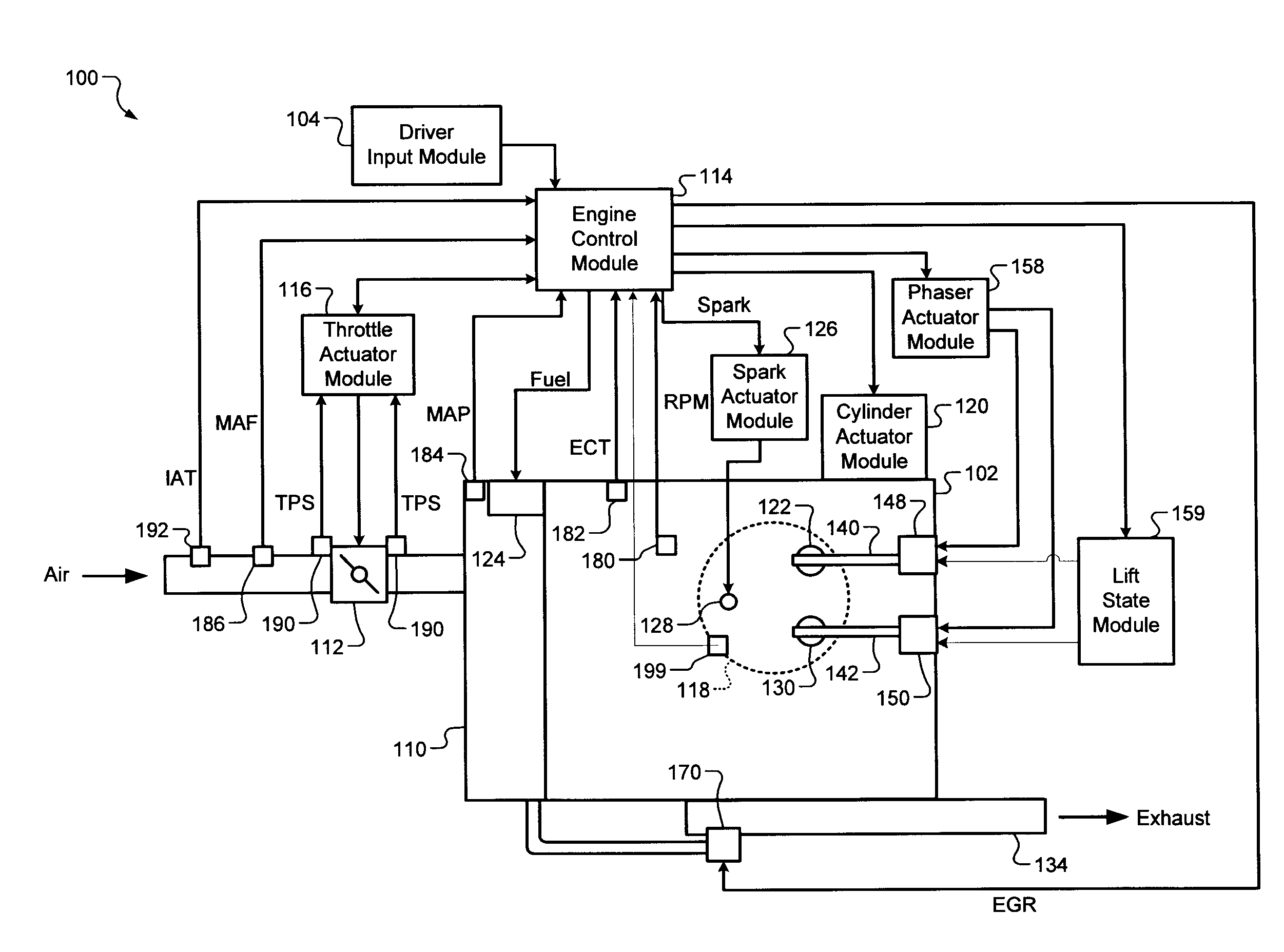
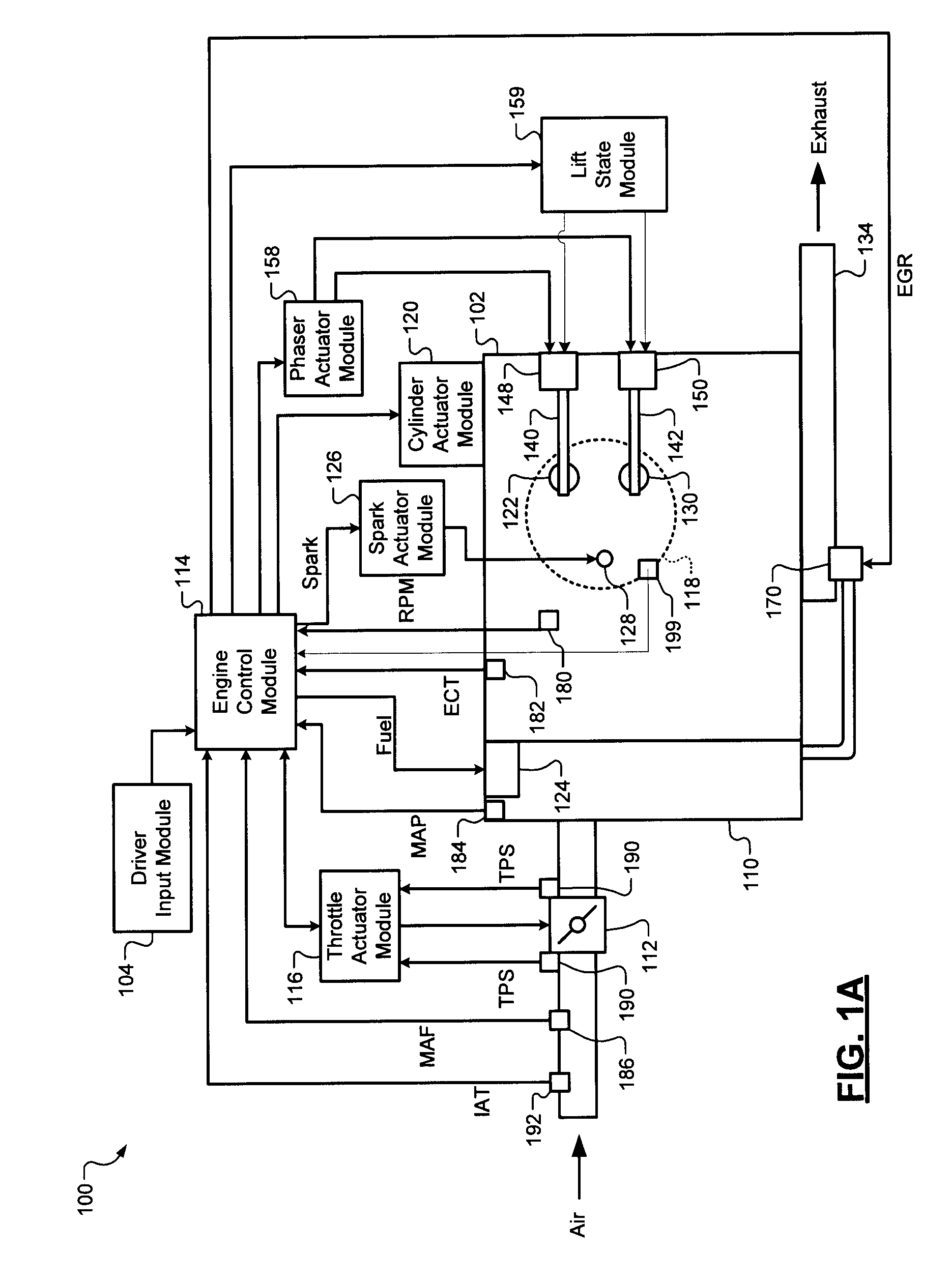
[0026]The engine control system according to the present disclosure operates the engine in a spark ignition (SI) mode or a ho...


PUM


Abstract

A control system for an engine comprises an air per cylinder (APC) generating module that generates measured and desired APC values. A combustion transition module selectively transitions the engine from spark ignition (SI) combustion to homogeneous charge compression ignition (HCCI) combustion and from HCCI combustion to SI combustion. A spark control module selectively retards spark during the transitions based on a ratio of the measured APC value and the desired APC value. Alternately, spark retard can be based on measured and desired engine torque representing values (ETRVs).

Description

CROSS-REFERENCE TO RELATED APPLICATIONS[0001]This application claims the benefit of U.S. Provisional Application No. 61 / 035,593, filed on Mar. 11, 2008. The disclosure of the above application is incorporated herein by reference in its entirety.FIELD OF THE INVENTION[0002]The present invention relates to engine control systems, and more particularly to engine control systems for engines operating in both spark ignition and homogenous charge compression ignition modes.BACKGROUND OF THE INVENTION[0003]The background description provided herein is for the purpose of generally presenting the context of the disclosure. Work of the presently named inventors, to the extent it is described in this background section, as well as aspects of the description that may not otherwise qualify as prior art at the time of filing, are neither expressly nor impliedly admitted as prior art against the present disclosure.[0004]Engines may be operated in a spark ignition (SI) mode and a homogeneous charge...

Claims


Application Information

Patent Timeline
Patent Type & Authority Applications(United States)
IPC IPC(8): F02B17/00
CPCF02B1/14F02B17/005F02D37/02F02D41/187F02D41/3035Y02T10/128F02D2041/002F02D2200/0402F02D2200/0406F02D2200/0414F02D2250/21F02D41/307Y02T10/12
Inventor RAMAPPAN, VIJAYRAYL, ALLEN B.KANG, JUN-MOKAFARNIK, PETERWILES, MATTHEW A.YUN, HANHO
Owner GM GLOBAL TECH OPERATIONS LLC
Why Eureka
Try Eureka