Engine control system

a control system and engine technology, applied in the direction of electric control, machines/engines, output power, etc., can solve the problems of abnormal combustion such as preignition, liable to promote the ignition of air-fuel mixture, etc., and achieve the effect of widening the engine load rang

Active Publication Date: 2013-01-24
MAZDA MOTOR CORP
View PDF2 Cites 12 Cited by
  • Summary
  • Abstract
  • Description
  • Claims
  • Application Information

AI Technical Summary

Benefits of technology

[0005]In view of the above circumstances, it is an object of the present invention to provide an engine control system capable of adequately controlling an amount of burned gas to be introduced into a cylinder of an engine, depending on an engine load, to allow HCCI combustion to be adequately performed in a wider engine load range.
[0006]An engine control system of the present invention is designed to allow homogeneous-charge compression ignition (HCCI) combustion to be performed in an HCCI region defined as an engine operating region including at least a partial-load range of an engine. The engine control system comprises a variable lift mechanism adapted to variably set a lift amount of an intake valve, a switching mechanism adapted to be capable of switching between allowing an exhaust valve to be opened both during an exhaust stroke and during an intake stroke, and allowing the exhaust valve to be opened only during the exhaust stroke, and a valve controller adapted to drive the variable lift mechanism and the switching mechanism to control respective opening / closing operations of the intake valve and the exhaust valve. In the engine control system, the HCCI region is divided into a plurality of load zones including a low load zone, and a medium load zone in which the engine load is higher than in the low load zone. The valve controller is operable, in the low load zone of the HCCI region, to set the lift amount of the intake valve to a first predetermined value and allow the exhaust valve to start being opened during the intake stroke at a given timing later than an opening timing of the intake valve, and, in the medium load zone of the HCCI region, to gradually increase the lift amount of the intake valve up to a second predetermined value greater than the first predetermined value, along with an increase in the engine load.

Problems solved by technology

However, if the operation of introducing the burned gas into the cylinder is continuously performed through an engine operating region where an engine load is relatively high (i.e., a fuel injection amount is relatively large), the auto-ignition of the air-fuel mixture is liable to be excessively promoted, which causes abnormal combustion such as preignition.

Method used


Image

  • Engine control system
  • Engine control system
  • Engine control system

Examples


Embodiment Construction

[0018](1) Overall Structure of Engine

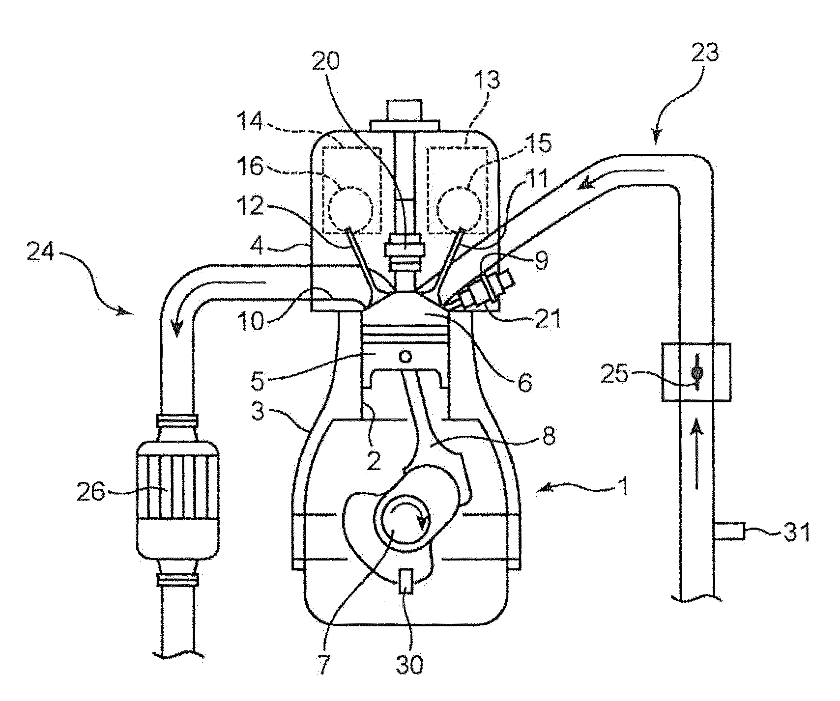
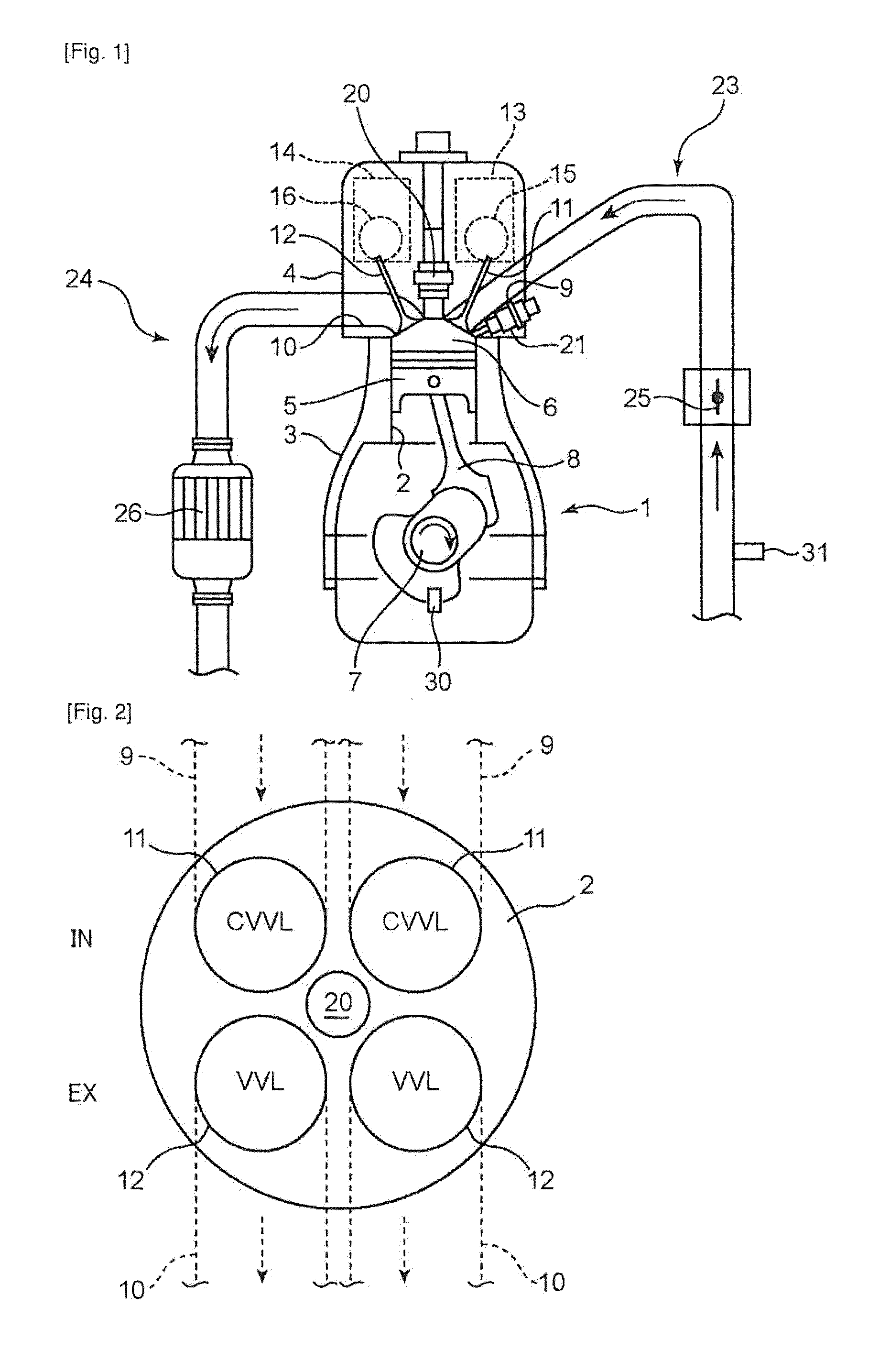
[0019]FIG. 1 is a schematic diagram showing an overall structure of an engine employing a control system according to one embodiment of the present invention. The engine illustrated in FIG. 1 is a reciprocating-piston type multicylinder gasoline engine to be mounted as a power source for driving of vehicle running. An engine body 1 of the engine comprises a cylinder block 3 having a plurality of cylinders 2 arranged side-by-side in a direction perpendicular to a surface of the drawing sheet (In FIG. 1, only one of the cylinders 2 is illustrated), a cylinder head 4 provided on an upper surface of the cylinder block 3, and a plurality of pistons 5 each inserted in a perspective one of the cylinders 2 in a reciprocatingly slideably manner. Fuel to be supplied to the engine body 1 may be any type consisting mainly of gasoline. For example, the fuel may consist only of gasoline, or may comprise gasoline and ethanol (ethyl alcohol) or the like containe...


PUM


Abstract

Disclosed is an engine control system which is designed to allow homogeneous-charge compression ignition combustion to be performed in an HCCI region (R) defined as an engine operating region including at least a partial-load range of an engine. In a low load zone (R1) of the HCCI region (R), a lift amount of an intake valve (11) is set to a first predetermined value, and an exhaust valve (12) is allowed to start being opened during an intake stroke at a given timing later than an opening timing of the intake valve (11). Further, in the medium load zone of the HCCI region, the lift amount of the intake valve (11) is gradually increased up to a second predetermined value greater than the first predetermined value, along with an increase in an engine load. The engine control system is capable of adequately controlling an amount of burned gas to be introduced into a cylinder, depending on the engine load to allow the HCCI combustion to be adequately performed in a wider engine load range.

Description

TECHNICAL FIELD[0001]The present invention relates to an engine control system designed to allow homogeneous-charge compression ignition (HCCI) combustion to be performed in an HCCI region defined as an engine operating region including at least a partial-load range of an engine, wherein the engine control system comprises a variable lift mechanism adapted to variably set a lift amount of an intake valve, a switching mechanism adapted to be capable of switching between allowing an exhaust valve to be opened both during an exhaust stroke and during an intake stroke and allowing the exhaust valve to be opened only during the exhaust stroke, and a valve controller adapted to drive the variable lift mechanism and the switching mechanism to control respective opening-closing operations of the intake valve and the exhaust valve.BACKGROUND ART[0002]Heretofore, in the field of gasoline engines, a combustion mode where an air-fuel mixture is forcibly ignited by a spark discharge from a spark...

Claims


Application Information

Patent Timeline
Patent Type & Authority Applications(United States)
IPC IPC(8): F01L1/34
CPCY02T10/47F02D13/0207F02D41/006Y02T10/128F02D2041/001F02D13/0273F02D41/3035Y02T10/42F02D41/0002Y02T10/18F02B1/02F02B1/12F02B11/00F02B11/02F02M26/01Y02T10/12Y02T10/40
Inventor NAGATSU, KAZUHIROHIDAKA, MASATOSHIKAMINAGA, TAKASHIYAMAKAWA, MASAHISA
Owner MAZDA MOTOR CORP
Why Eureka
Try Eureka