In-line filter/flow regulator/Anti-siphon device

a technology of flow regulator and filter, which is applied in the direction of mechanical equipment, transportation and packaging, and functional valve types, etc., can solve the problems of affecting the flow of water, affecting the efficiency of the device, so as to achieve the effect of reducing fluid flow and pressur

Inactive Publication Date: 2009-09-17
ORBIT IRRIGATION PRODS
View PDF53 Cites 2 Cited by
  • Summary
  • Abstract
  • Description
  • Claims
  • Application Information

AI Technical Summary

Benefits of technology

[0012]The flow regulator section includes a flow regulator piston disposed within a flow regulator chamber. The flow regulator piston has a narrow region, a frusto-conical region, an external groove, and a pressure lip. The flow regulator chamber defines one or more openings for fluid entry disposed proximate the narrow region of the flow regulator piston. A flow regulator spring biases the flow regulator piston in an open state. When the fluid flows through the flow regulator section, the flow regulator piston applies sufficient pressure to the pressure lip to counterbalanc...

Problems solved by technology

Distributing fluid through a hose can create a host of different problems.
For example, contaminants within the hose can backflow into a water source, polluting the water source (such as the water supply of a house).
Furthermore, fluid distributed via a hose can often have uneven water pressure, particularly when the fluid is initially turned on, causing sprinklers and hose nozzles attached ...

Method used


Image

  • In-line filter/flow regulator/Anti-siphon device
  • In-line filter/flow regulator/Anti-siphon device
  • In-line filter/flow regulator/Anti-siphon device

Examples


Embodiment Construction

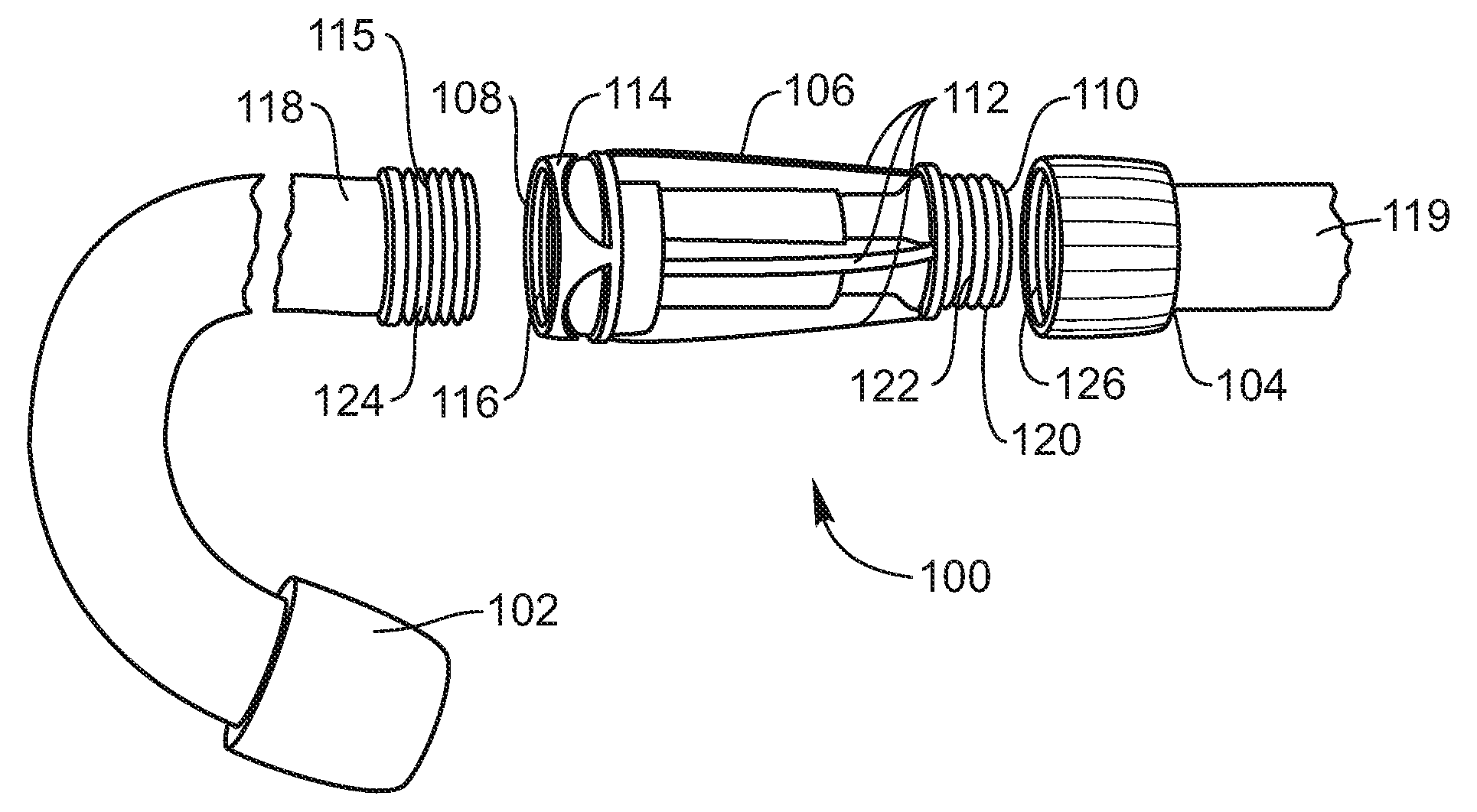
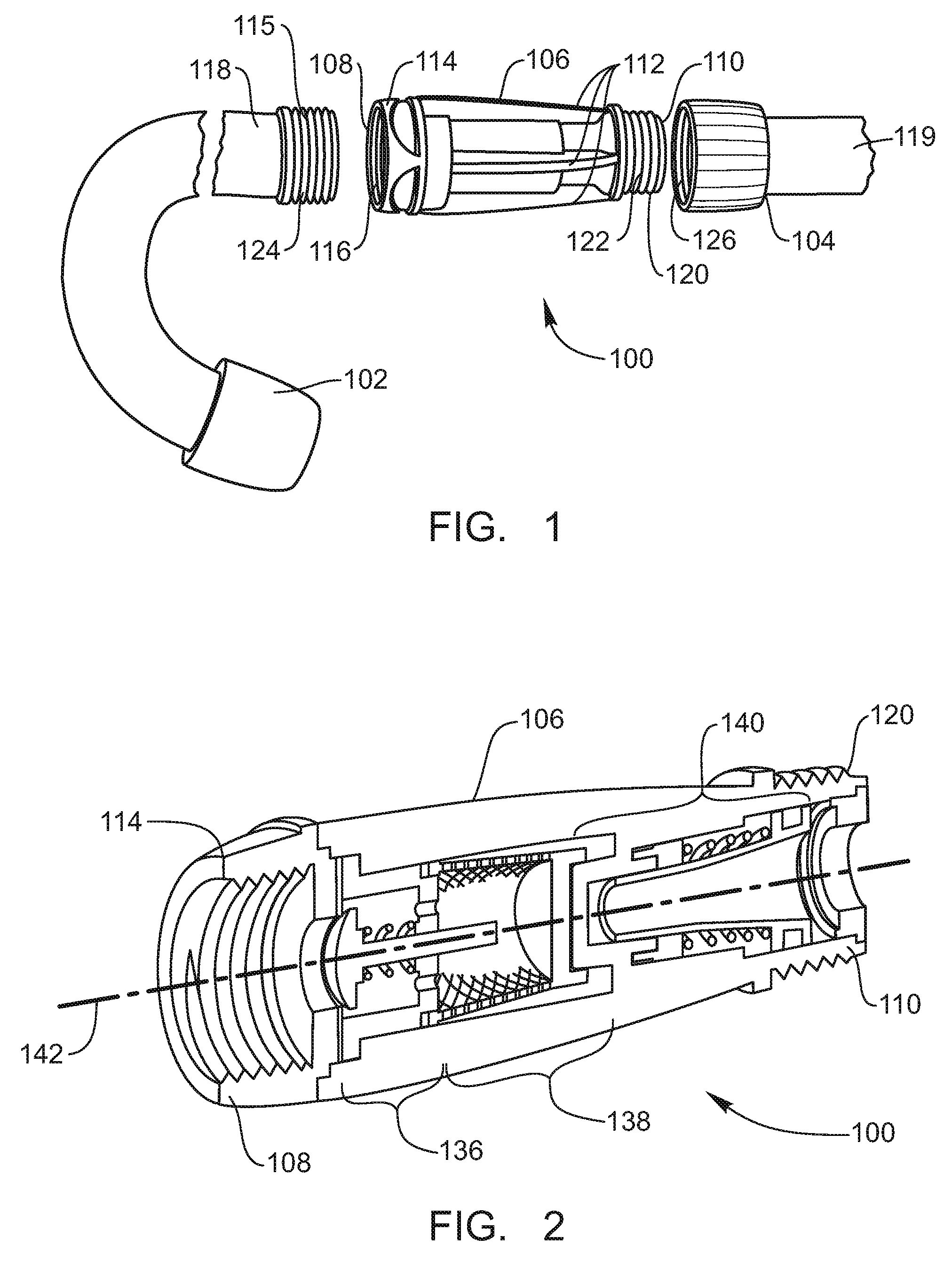
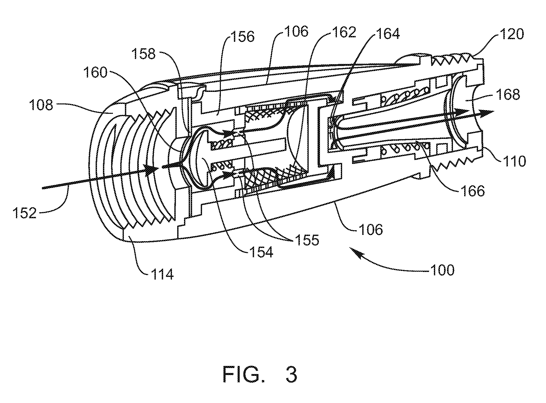
[0022]The presently preferred embodiments of the invention will be best understood by reference to the drawings, wherein like parts are designated by like numerals throughout. It will be readily understood that the components of the present invention, as generally described and illustrated in the figures herein, could be arranged and designed in a wide variety of different configurations. Thus, the following more detailed description of the embodiments of the present invention, as represented in FIGS. 1 through 8, is not intended to limit the scope of the invention, as claimed, but is merely representative of presently preferred embodiments of the invention.

[0023]As used herein, the term “in fluid communication with” means that fluid, if present, could pass from a first identified fluid passageway, object, opening, or aperture to a second fluid passageway, object, opening, or aperture. This term does not require that fluid be actually present within any of the identified fluid passa...


PUM


Abstract

An in-line, hose-end filter/flow regulator/anti-siphon device is disclosed. The disclosed hose-end device includes a unitary body having a generally linear side profile, a first end, a second end, and a longitudinal axis. An inlet hose-end receptor is disposed on the first end, while an outlet hose-end receptor is disposed on the second end. An anti-siphon section, a filter section, and a flow regulator section are positioned between the first end and the second end. The inlet hose-end receptor, the anti-siphon section, the filter section, the flow regulator section, and the outlet hose-end receptor are coaxial with the longitudinal axis of the body.

Description

BACKGROUND OF THE INVENTION[0001]Distributing fluid through a hose can create a host of different problems. For example, contaminants within the hose can backflow into a water source, polluting the water source (such as the water supply of a house).[0002]Also, filtering fluid within a hose can be important to protect hose nozzles, hose-end sprinklers, and other hose-end products from becoming clogged due to debris within the hose. Furthermore, fluid distributed via a hose can often have uneven water pressure, particularly when the fluid is initially turned on, causing sprinklers and hose nozzles attached to the hose to perform erratically.[0003]Addressing each of these problems independently would require a cumbersome and awkward conglomeration of devices, making it very difficult to utilize the devices together. Further, assembling a number of different devices to address these problems could be expensive, and the operation of one of these devices may interfere with the operation o...

Claims


Application Information

Patent Timeline
IPC IPC(8): F16K24/00
CPCE03C1/104E03C2001/026F16K15/063F16K15/026E03C2201/40Y10T137/3149
Inventor HOSKISSON, SCOTWANGSGAARD, TRES
Owner ORBIT IRRIGATION PRODS
Why Eureka
Try Eureka