Self-Contained Tensioned Roller Shade System
a self-contained, tensioned technology, applied in the direction of shutters/movable grilles, curtain suspension devices, door/window protective devices, etc., can solve the problems of limiting the size (i.e., the length) of the shade fabric, and the inability to separate the motors of the “dual-motor” shade system
- Summary
- Abstract
- Description
- Claims
- Application Information
AI Technical Summary
Benefits of technology
Problems solved by technology
Method used
Image
Examples
second embodiment
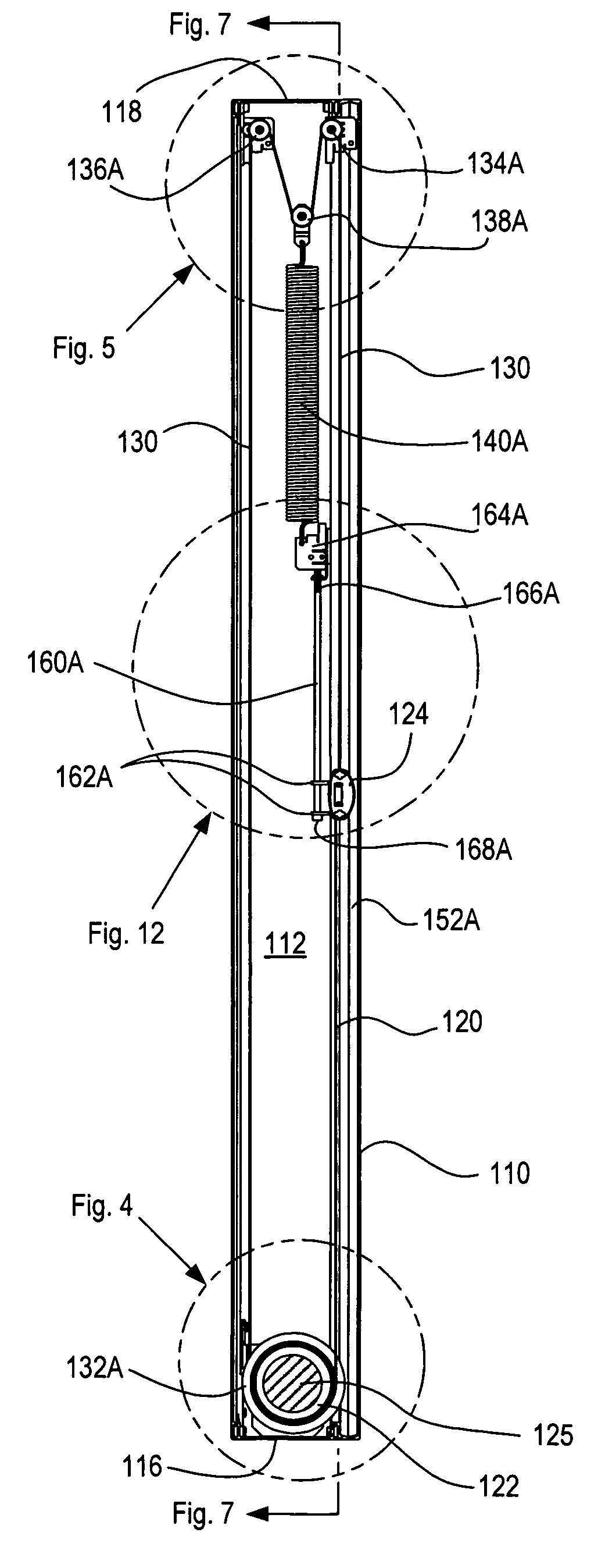
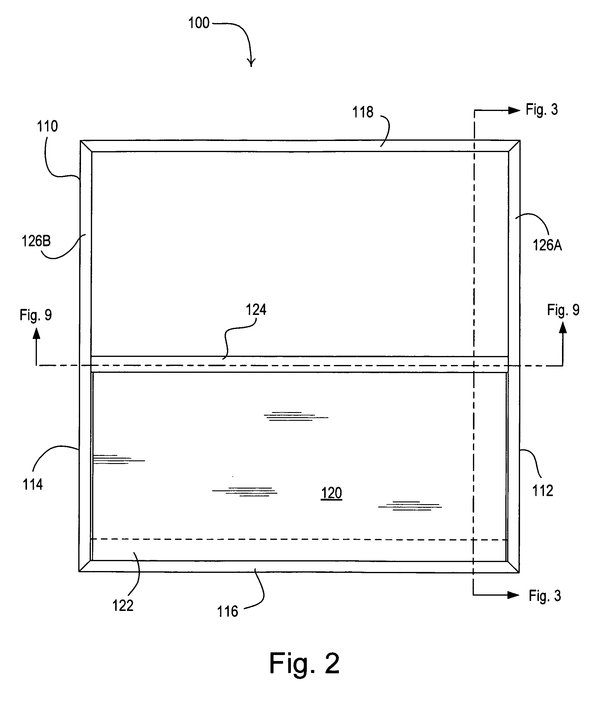
[0054]FIG. 13 is a left-side cross-sectional view of a roller shade system 200 according to the present invention. Note that the view of FIG. 13 is taken across the same sectional line as FIG. 3 (i.e., as shown in FIG. 2). Rather than including three separate pulleys 134A, 136A, 138A in the first side channel 112, the roller shade system 200 of FIG. 13 includes one single pulley 138A and one dual pulley 234A, which comprises two pulleys located immediately adjacent each other and operable to rotate about the same axis. FIG. 13a is a simplified left-side schematic view of the roller shade system 200 showing the interaction between the shade fabric 120, the roller tube 122, the hembar 124, the tensioning cord 130, the pulleys 234A, 138A, and the spring 140A. The tensioning cord 130 is windingly received by the both pulleys of the dual pulley 234A. The third pulley 138A windingly receives a portion of the tensioning cord between the portions of the tensioning cord presently received by...
fourth embodiment
[0057]As described above, the roller shade system 100, 200, 300 is tensioned by springs 140A, 140B located in and attached to the side channels 112, 114. However, the locations of the springs of the present invention are not limited to the side channels 112, 114. FIG. 15 is a simplified front schematic view of a roller shade system 400 according to the present invention. The roller shade system 400 includes two separate tensioning cords (i.e., first and second tensioning cord portions 430A, 430B), which are windingly received around respective pulleys 438A, 438B in the respective side channels 112, 114. A single spring 470 is located inside the hembar 124 and is coupled between the first and second tensioning cord portions 430A, 430B to provide for the appropriate tensioning of the roller shade system 400. An example of a roller shade system having a spring located inside the hembar is described in greater detail in U.S. Pat. No. 1,121,898, issued Dec. 22, 1914, entitled WINDOW SCRE...
fifth embodiment
[0058]FIG. 16 is a simplified front schematic view of a roller shade system 500 according to the present invention. In the roller shade system 500, first and second tensioning cord portions 530A, 530B are formed as part of a single tensioning cord (i.e., tensioning cord 530). The roller shade system 500 comprises a single spring 570, which is located in the second frame end 118 and has a first spring pulley 572A at a first spring end and a second spring pulley 572B at a second spring end. The roller shade system 500 further comprises two pulleys 536A, 538A located in the first side channel 112 adjacent the second frame end 118, and two pulleys 536B, 538B located in the second side channel 114 adjacent the second frame end. The pulleys 536A, 538A in the first side channel 112 operate to guide the first tensioning cord portion 530A towards the first spring pulley 572A, which windingly receives the first tensioning cord portion. The pulleys 536B, 538B in the second side channel 114 ope...
PUM
 Abstract
Description
Claims
Application Information
 - R&D
- Intellectual Property
- Life Sciences
- Materials
- Tech Scout
- Unparalleled Data Quality
- Higher Quality Content
- 60% Fewer Hallucinations
Browse by: Latest US Patents, China's latest patents, Technical Efficacy Thesaurus, Application Domain, Technology Topic, Popular Technical Reports.
© 2025 PatSnap. All rights reserved.Legal|Privacy policy|Modern Slavery Act Transparency Statement|Sitemap|About US| Contact US: help@patsnap.com


