
Image heating apparatus and heater used for the image heating apparatus

Inactive Publication Date: 2009-09-17
CANON KK
View PDF23 Cites 93 Cited by
  • Summary
  • Abstract
  • Description
  • Claims
  • Application Information

AI Technical Summary

Benefits of technology

[0012]The present invention has been accomplished with respect to the above described problems, and provides an image heating apparatus which simultaneously prevents the temperature in a non-sheet feeding portion from rising and secures fixing properties in a gap between the divided heat generating resistors, and a heater used in this image heating apparatus.

Problems solved by technology

When the non-feeding region of the heater excessively raises its temperature, the heat occasionally damages the holder which holds the heater and the pressure roller.
However, a heat generating resistor having the negative resistance-temperature characteristics generally has high volume resistance, and it is often difficult to obtain electric resistance in a range in which a commercial power source is usable, from a normal heat generating resistor pattern.

Method used


Image

  • Image heating apparatus and heater used for the image heating apparatus
  • Image heating apparatus and heater used for the image heating apparatus
  • Image heating apparatus and heater used for the image heating apparatus

Examples


exemplary embodiment 1

[0155]substrate of aluminum oxide: 20 W / m·K overcoat layer: 2 W / m·K

exemplary embodiment 2

Present Exemplary Embodiment 2

[0156]substrate of aluminum nitride: 170 W / m·K insulating layer / sliding layer: 2 W / m·K

TABLE 4Comparison of heat resistanceheat resistanceratio of heat(×10−6K / W)resistancestopsidebackside(topside surfacesurfacesurfaceside / backsideheating membersidesidesurface side)exemplary embodiment 125.050.00.50(topside-surfaceheat-generation type)present exemplary8.525.00.34embodiment 2 (backside-surface heat-generation type)

[0157]A ratio of heat resistances in Table 4 is a value obtained by dividing the heat resistance in the topside surface side by the heat resistance in the backside surface side. As the value is smaller, the heat resistance in the topside surface side becomes smaller than that in the backside surface side, and accordingly the fixing efficiency is more excellent.

[0158]As is illustrated in Table 4, the heating member 3 in the present exemplary embodiment 2 has a smaller ratio of the heat resistances than that in the heating member 3 of Exemplary emb...


PUM


Abstract

The image heating apparatus includes a heater has a first and heat-generation segment having a plurality of heat generating parts therein in the longitudinal direction respectively, and the heat generating parts each having a first electro-conductive pattern provided along the longitudinal direction on a substrate, and a second electro-conductive pattern provided along the longitudinal direction on said substrate and has a region that overlaps with said first electro-conductive pattern in the longitudinal direction, and a heat generating resistor which electrically connects the respective overlapping regions of said first electro-conductive pattern and said second electro-conductive pattern with each other and generates heat by a supplied electric power. It simultaneously prevents the temperature in a non-sheet feeding portion from rising and secures fixing properties in a gap between the divided heat generating resistors, and a heater used in this image heating apparatus.

Description

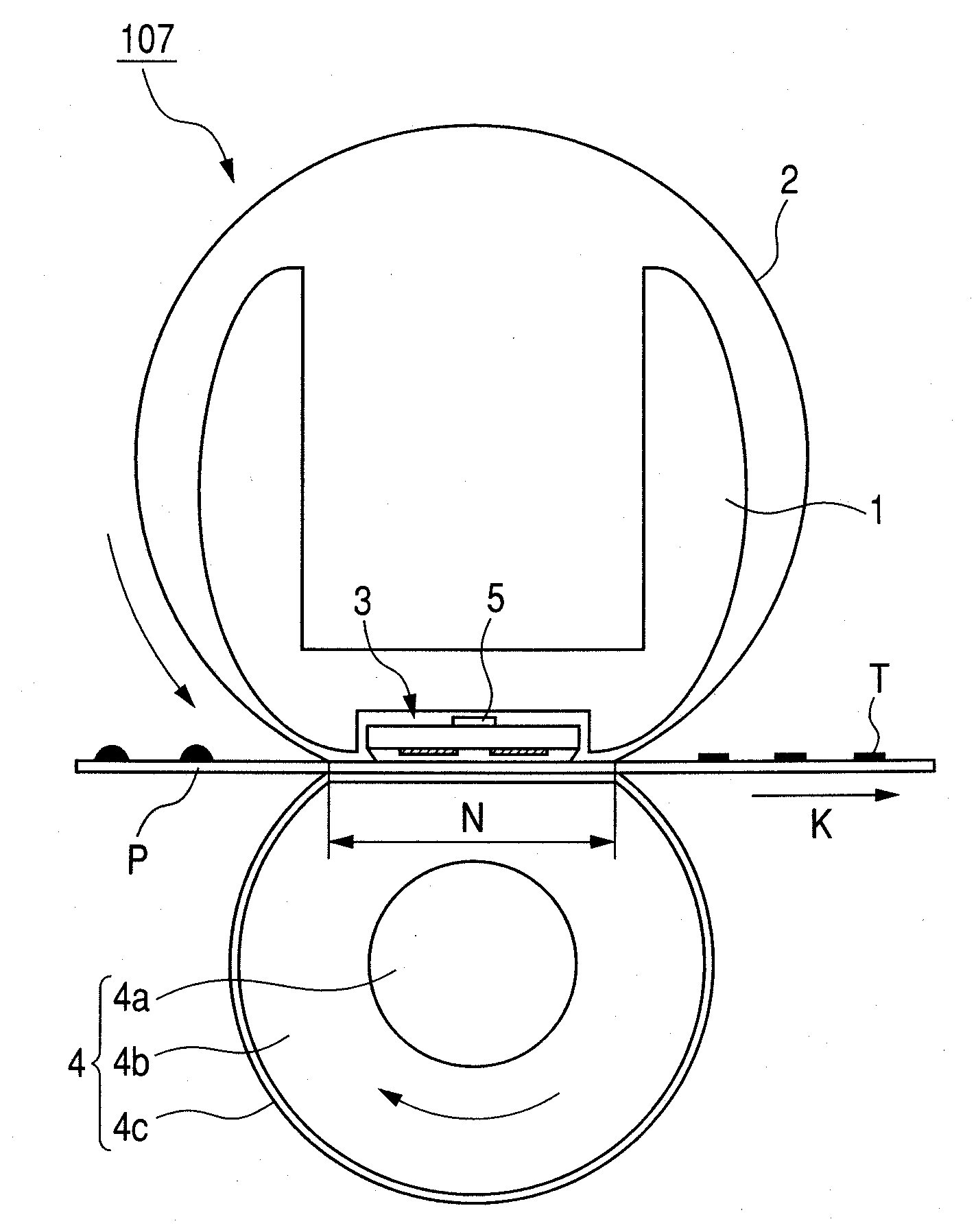
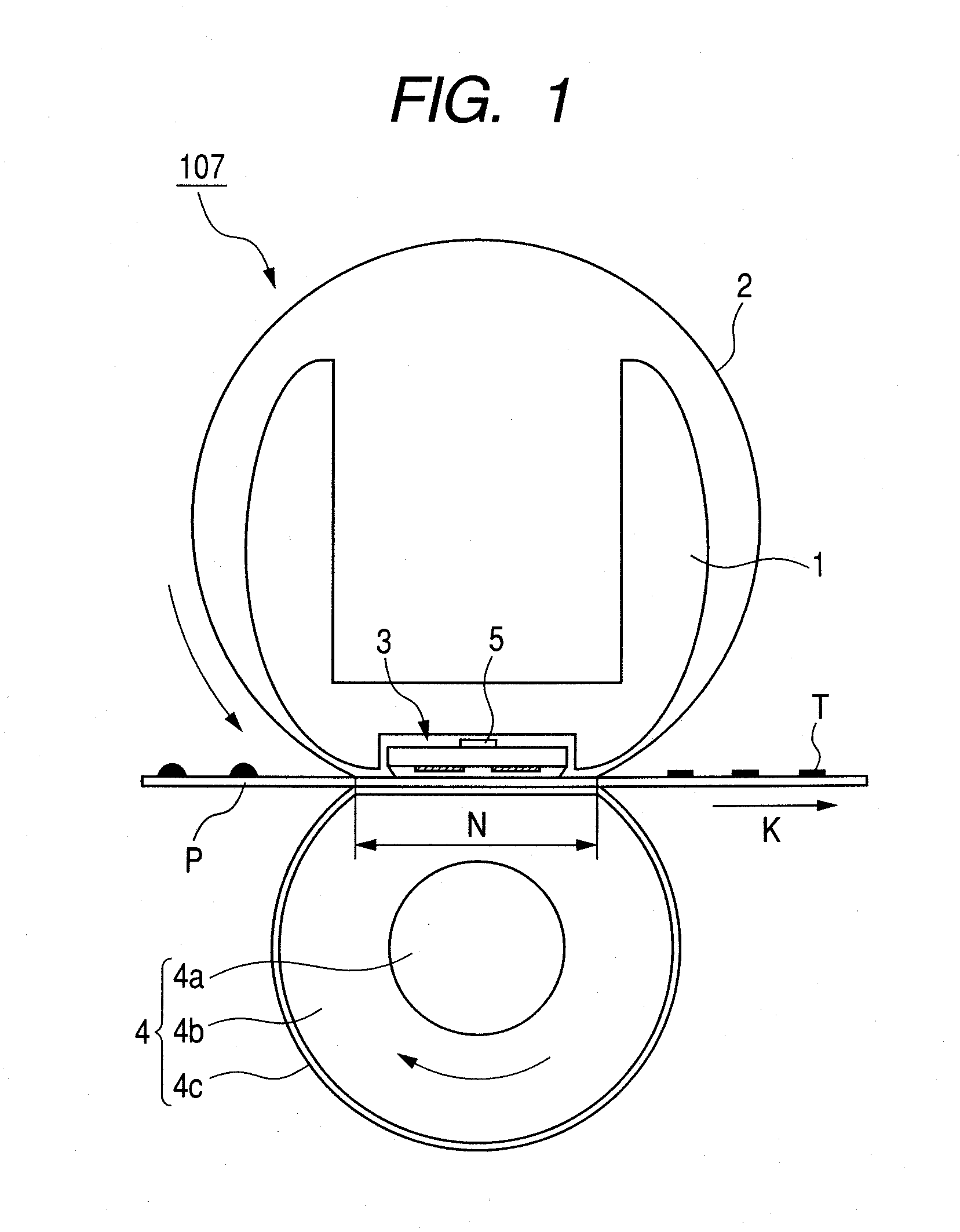
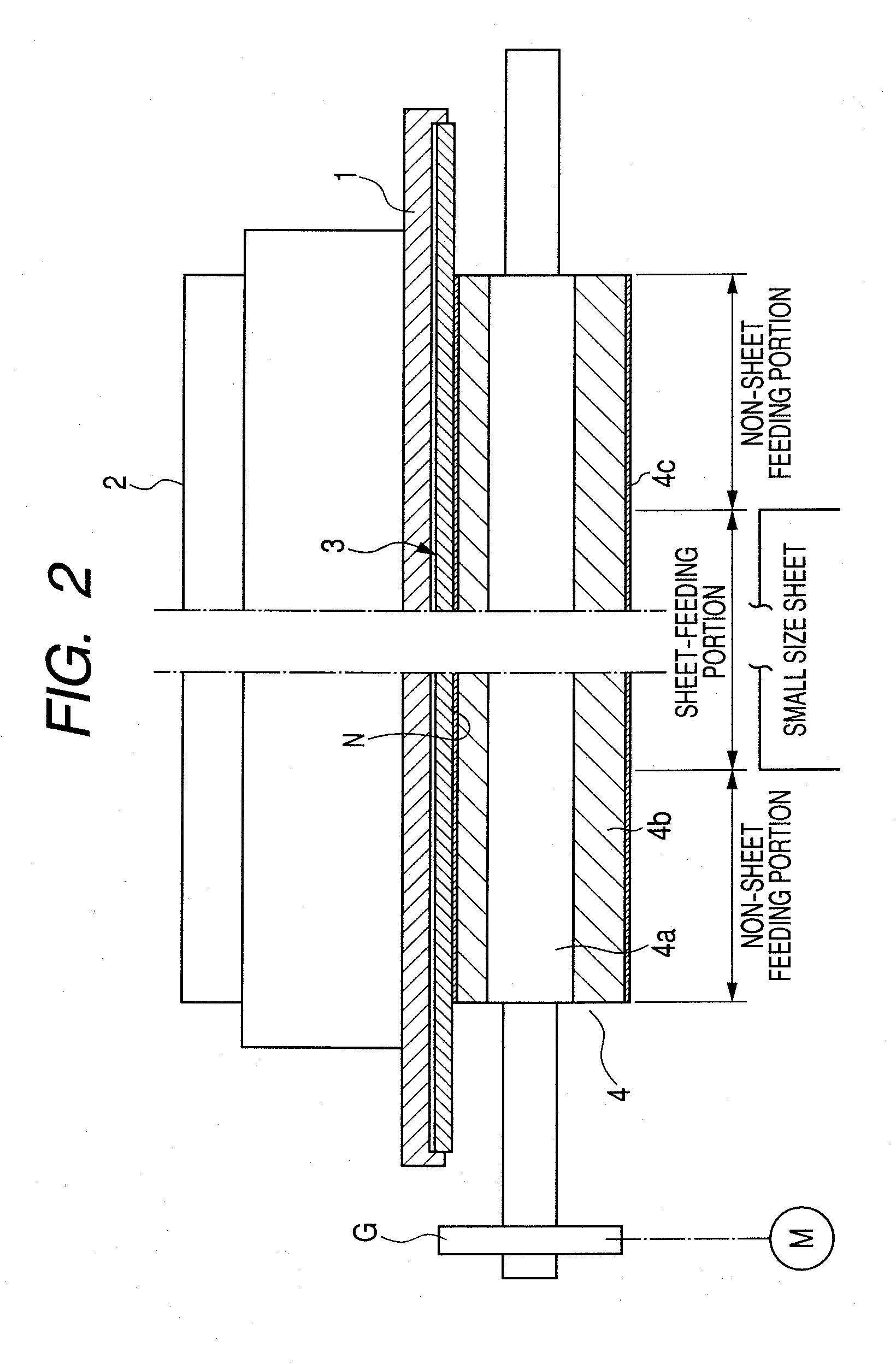
BACKGROUND OF THE INVENTION[0001]1. Field of the Invention[0002]The present invention relates to an image heating apparatus which can be used as a heating and fixing apparatus (fixing device) that is mounted on an image forming apparatus such as an electrophotographic copying machine and an electrophotographic printer, and to a heater used for the image heating apparatus.[0003]2. Description of the Related Art[0004]Some heating and fixing apparatuses (fixing device) which are mounted on an electrophotographic printer or an electrophotographic copying machine have a heater having a heat generating resistor on a substrate made from ceramic, a flexible member (fixing film) which moves while contacting with the heater, and a pressure roller which forms a nipping portion with the heater through the flexible member. A recording medium which carries an unfixed toner image thereon is heated while being sandwiched in the nipping portion of the fixing device and transported therethrough, and ...

Claims


Application Information

Patent Timeline
IPC IPC(8): H05B1/00
CPCG03G15/2042
Inventor TANIGUCHI, SATORUHASEGAWA, HIROTO
Owner CANON KK
Learn More