Method for forming dynamic pressure generating grooves

Inactive Publication Date: 2009-09-17
NTN CORP
View PDF6 Cites 10 Cited by
  • Summary
  • Abstract
  • Description
  • Claims
  • Application Information

AI Technical Summary

Benefits of technology

[0016]As described above, according to the present invention, dynamic pressure generating grooves can be molded highly precisely and at low cost. Al

Problems solved by technology

The price, on the other hand, of information equipment is going down, which m

Method used


Image

  • Method for forming dynamic pressure generating grooves
  • Method for forming dynamic pressure generating grooves
  • Method for forming dynamic pressure generating grooves

Examples


Embodiment Construction

[0017]Embodiments of the present invention will be hereinafter described with reference to the drawings.

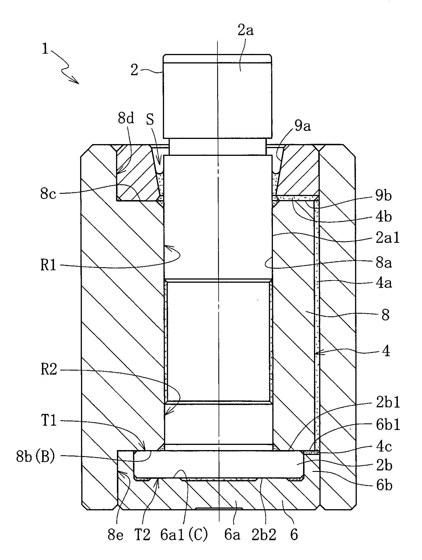
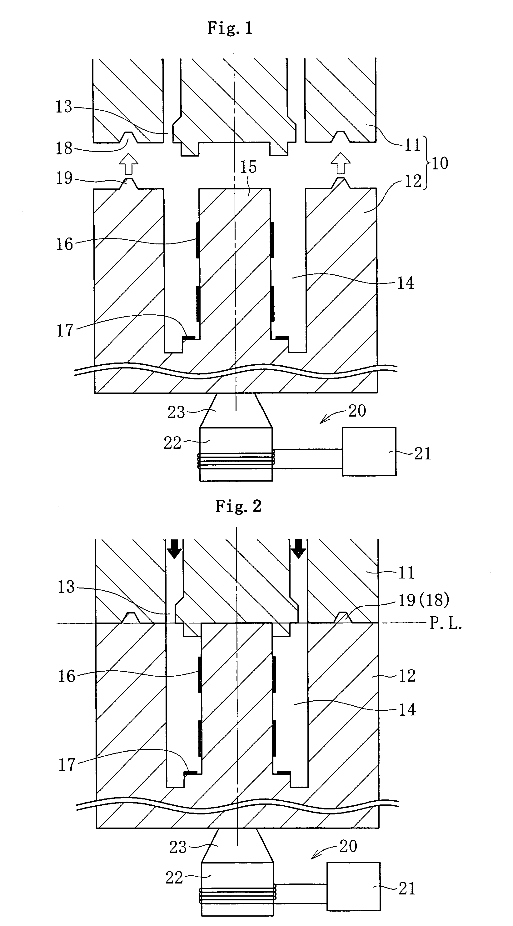
[0018]FIG. 1 shows one example of a molding apparatus used for molding dynamic pressure generating grooves that generate fluid dynamic pressure in bearing gaps. Here is given a schematic illustration of an injection molding apparatus used for molding dynamic pressure generating grooves on the inner circumferential surface 8a and on one end face (lower end face 8b in FIG. 4) of a bearing member 8 (see FIG. 4), which is a resin injection-molded fixed member.

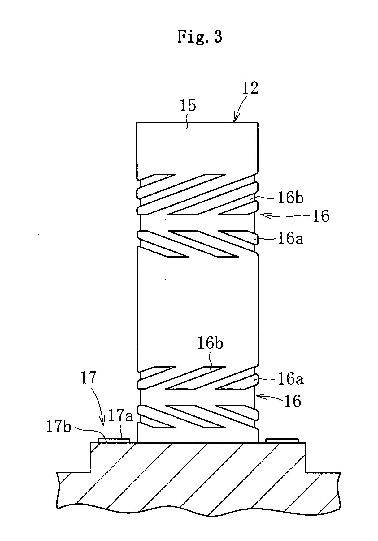
[0019]The injection molding apparatus includes, as major constituent elements, an injection mold 10 consisting of a fixed mold half 11 held by suitable means (not shown) and a movable mold half 12 set coaxially with the fixed mold half 11, and an ultrasonic generating device 20 that applies ultrasonic vibration to the injection mold 10.

[0020]The injection mold 10 is made of a metal material having excellent ultrasonic vibration t...


PUM

PropertyMeasurementUnit
Pressureaaaaaaaaaa

Abstract

High-precision, low-cost molding of dynamic pressure generating grooves is made possible.
An ultrasonic generating device 20 is connected to an injection mold 10. The dynamic pressure generating grooves are molded by means of radial dynamic pressure generating groove forming parts 16 and a thrust dynamic pressure generating groove forming part 17 provided in the injection mold 10, with ultrasonic vibration generated by the ultrasonic generating device 20 being applied to the injection mold 10 during the injection molding.

Description

TECHNICAL FIELD[0001]The present invention relates to a method for forming dynamic pressure generating grooves that generate fluid dynamic pressure in bearing gaps.BACKGROUND ART[0002]Fluid dynamic bearing devices are widely used as the bearing of spindle motors that are mounted in information equipment such as HDDs or other magnetic disk devices, CD-ROMs, CD-R / RWs, DVD-ROM / RAMs or other optical disk devices, MDs, MOs or other magnetic optical disk devices, of polygon scanner motors mounted in laser beam printers (LBP) or the like, of fan motors mounted in personal computers (PC), or of small motors mounted in electrical equipment such as axial fans.[0003]High rotation precision, high speed, and low noise are the requirements for the various types of motors listed above. One of the constituent elements of the motor that determines these performance requirements is the bearing that supports the spindle, and the fluid dynamic bearing device which is excellent in the above characterist...

Claims


Application Information

Patent Timeline
IPC IPC(8): B29C45/17
CPCB22F3/225B29C45/0046B29C45/568F16C2370/12F16C17/107F16C33/107B29L2031/04B29C45/17B29C45/40F16C33/20
Inventor SATOJI, FUMINORIITO, KENJI
Owner NTN CORP
Why Eureka
Try Eureka