

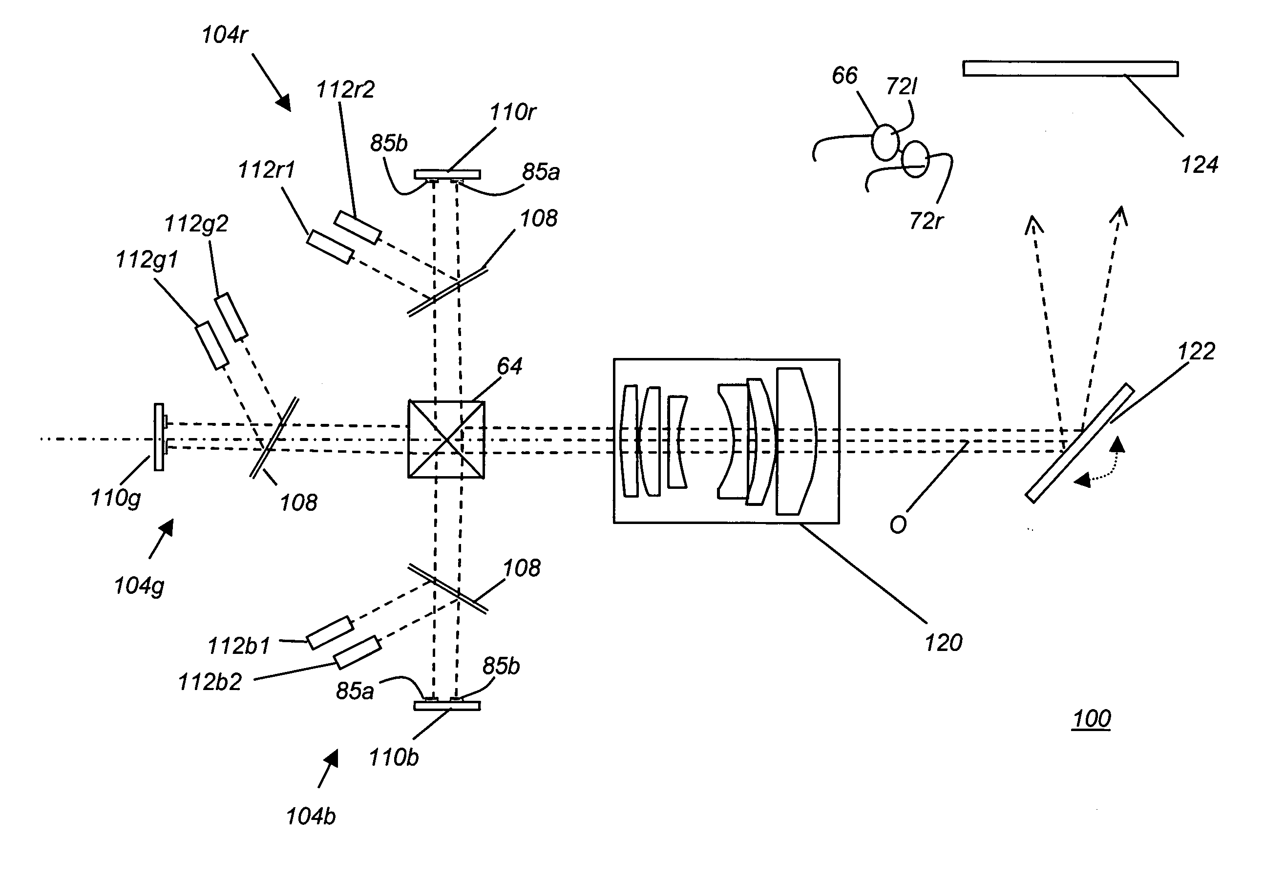
Stereoscopic display using multi-linear electromechanical modulator
a multi-linear, electromechanical modulator technology, applied in the field of display apparatus, can solve the problems of imposing additional requirements on theater design and layout, system cost, and the inability to meet the requirements of robust display apparatus, so as to reduce the complexity and reduce the requirements of optical alignment
- Summary
- Abstract
- Description
- Claims
- Application Information
AI Technical Summary
Benefits of technology
Problems solved by technology
Method used
Image

Examples
Embodiment Construction
[0034]The present description is directed in particular to elements forming part of, or cooperating more directly with, apparatus in accordance with the invention. It is to be understood that elements not specifically shown or described may take various forms well known to those skilled in the art. Figures shown and described herein are provided in order to illustrate key principles of operation of the present invention and are not drawn with intent to show actual size or scale. Some exaggeration may be necessary in order to emphasize relative spatial relationships or principles of operation.
[0035]In the following disclosure, the phrase “left-eye image” denotes the image formed by a display apparatus and intended for viewing by the left eye of the viewer. Likewise, the phrase “right-eye image” refers to the image that is intended for viewing from the right eye of the viewer.
[0036]In the context of the present invention, the term “spectral range” refers to a single wavelength or to a...
PUM
 Abstract
Description
Claims
Application Information