Vehicle headlamp apparatus

a headlamp and vehicle technology, applied in the field of vehicle headlamps, can solve the problems of insufficient driving of the vehicle, dimmed portion becomes dark, and the driver of the preceding vehicle may be glare-generating,

Active Publication Date: 2009-09-17
KOITO MFG CO LTD
View PDF19 Cites 33 Cited by
  • Summary
  • Abstract
  • Description
  • Claims
  • Application Information

AI Technical Summary

Benefits of technology

[0007]Illustrative aspects of the present invention provide a vehicle headlamp apparatus capable of suppressing glare given to a preceding vehicle and/or a pedestrian

Problems solved by technology

However, if light emitted from the headlamps is irradiated to an upper area which is located higher than a so-called “cutoff line”, then there are some risks that glare may be generated for drivers of preceding vehicles (i.e., vehicles traveling in front of the vehicle and in the same direction as the vehicle) and also pedestrians who are present in areas in front of the vehicles.
However, on the other hand, the vehicle drivers may see that thi

Method used


Image

  • Vehicle headlamp apparatus
  • Vehicle headlamp apparatus
  • Vehicle headlamp apparatus

Examples


first exemplary embodiment

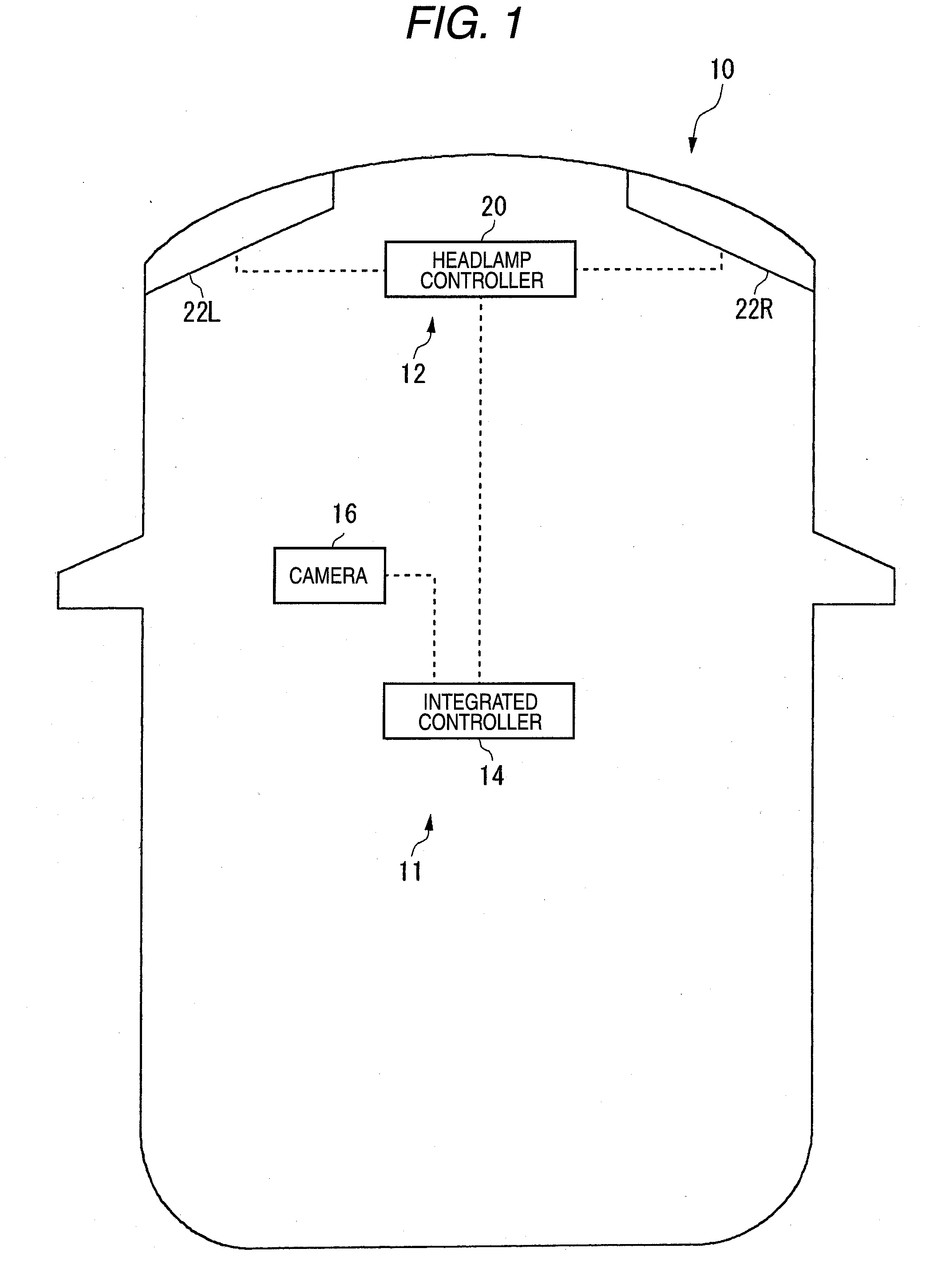
[0032]FIG. 1 is a schematic diagram of a vehicle 10 on which a headlamp apparatus 11 according to an exemplary embodiment of the present invention is mounted. The headlamp apparatus 11 includes a headlamp section 12, an integrated controller 14, and a camera 16 (a vehicle position detector).

[0033]The integrated controller 14 includes a central processing unit (CPU) for executing various calculating process operations, a read only memory (ROM) in which various control programs are stored in advance, a random access memory (RAM) which is utilized in order to store data and also used as a work area for executing relevant programs, and the like. The integrated controller 14 executes various control operations within the vehicle 10. The camera 16 includes an imaging element, for example, a charge coupled device (CCD) sensor, a complementary metal oxide semiconductor (CMOS) sensor. The camera 16 captures an image of a forward region of the vehicle to produce image data. The camera 16 is c...

second exemplary embodiment

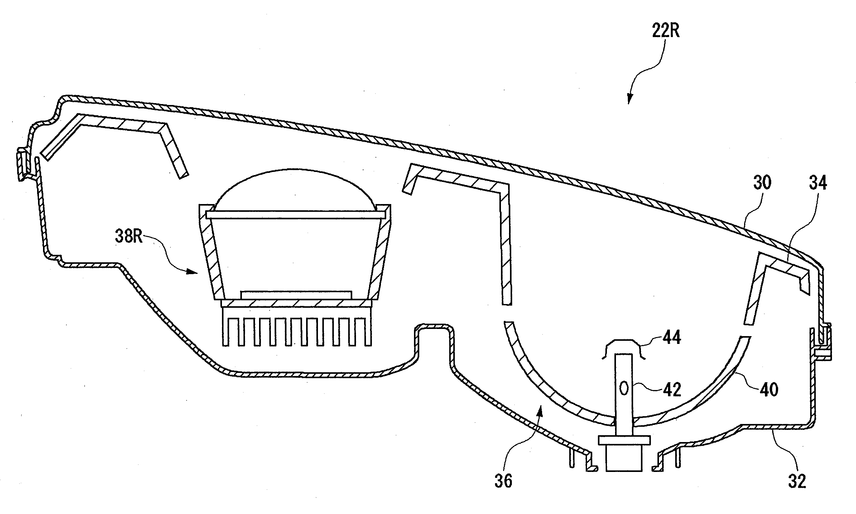
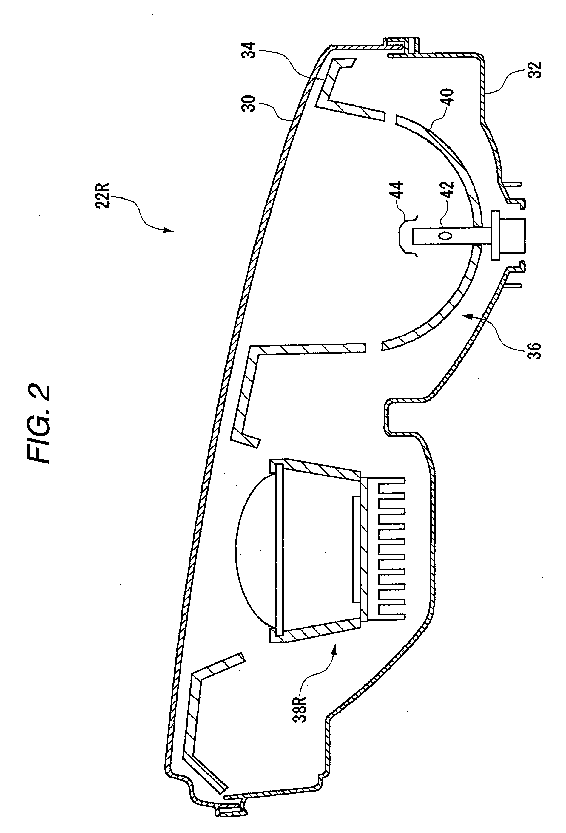
[0070]FIG. 11 is a sectional view of a right headlamp 60R according to a second exemplary embodiment of the present invention, taken along a horizontal plane and viewed from above. It should be noted that a configuration of a vehicle according to the second exemplary embodiment is similar to the configuration of the vehicle 10 according to the first exemplary embodiment except that the right headlamp 60R and a left headlamp 60L are provided instead of the right headlamp 22R and the left headlamp 22L. It should also be noted that the same reference numerals will be used to denote structural elements of the vehicle of the second exemplary embodiment that are similar to those of the vehicle 10 according to the first exemplary embodiment. The left headlamp 60L is constructed in a right-left symmetrical manner with respect to the right headlamp 60R. Therefore, the right headlamp 60R will be explained in detail below and a detailed explanation of the left headlamp 60L will be omitted.

[007...


PUM


Abstract

A vehicle headlamp apparatus is provided. The vehicle headlamp apparatus includes a lamp unit, a first additional lamp unit which forms a first light distribution pattern, a second additional lamp unit which forms a second light distribution pattern overlapping with the first light distribution pattern, and a controller. The first light distribution pattern includes at least one first partial region, and the first additional lamp unit adjusts a luminous intensity of a light to be irradiated toward the first partial region. The second light distribution pattern includes at least one second partial region which partially overlaps with the first partial region, and the second additional lamp unit adjusts a luminous intensity of a light to be irradiated toward the second partial region. The controller controls the first additional lamp unit and the second additional lamp unit to adjust the luminous intensity of the partial regions.

Description

CROSS-REFERENCE TO RELATED APPLICATION[0001]The present application claims priority from Japanese Patent Application No. 2008-062672 filed on Mar. 12, 2008, the entire content of which is incorporated herein by reference.FIELD OF INVENTION[0002]Apparatuses consistent with the present invention relate to vehicle headlamps.DESCRIPTION OF RELATED ART[0003]When vehicles are driven at nighttime, headlamps are normally turned on in a so-called “low beam” mode so as to illuminate surfaces of roads, and if necessary, the headlamps are turned on in a so-called “high beam” mode so as to better view regions in front of the vehicles. However, if light emitted from the headlamps is irradiated to an upper area which is located higher than a so-called “cutoff line”, then there are some risks that glare may be generated for drivers of preceding vehicles (i.e., vehicles traveling in front of the vehicle and in the same direction as the vehicle) and also pedestrians who are present in areas in front ...

Claims


Application Information

Patent Timeline
IPC IPC(8): B60Q1/00
CPCB60Q1/085B60Q2300/054B60Q2300/056B60Q2300/41B60Q2300/42B60Q2300/45F21Y2101/02F21S48/1159F21S48/1163F21S48/1241F21S48/1747F21S48/25F21S48/1154F21Y2115/10F21S41/143F21S41/155F21S41/24F21S41/663F21S43/50F21S41/151
Inventor YAMAMURA, SATOSHI
Owner KOITO MFG CO LTD
Why Eureka
Try Eureka