

Temperature Detector and Fixing Material Transfer Suppressing Structure
- Summary
- Abstract
- Description
- Claims
- Application Information
AI Technical Summary
Benefits of technology
Problems solved by technology
Method used
Image

Examples
first embodiment
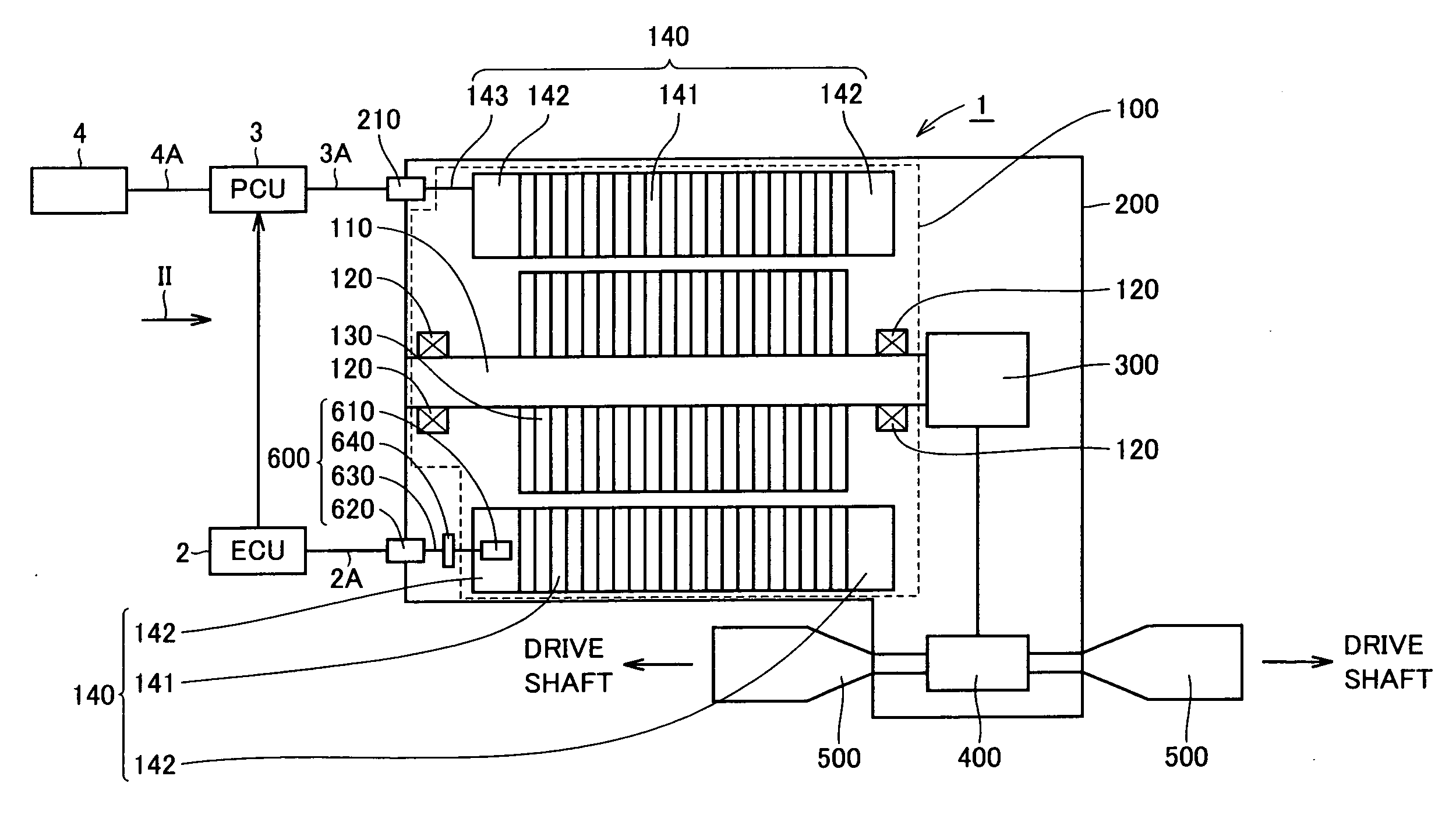
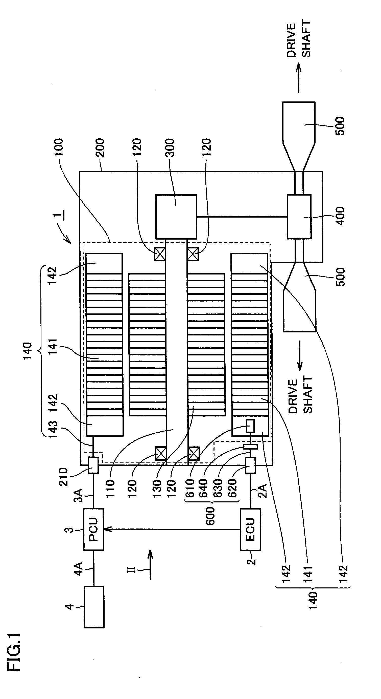
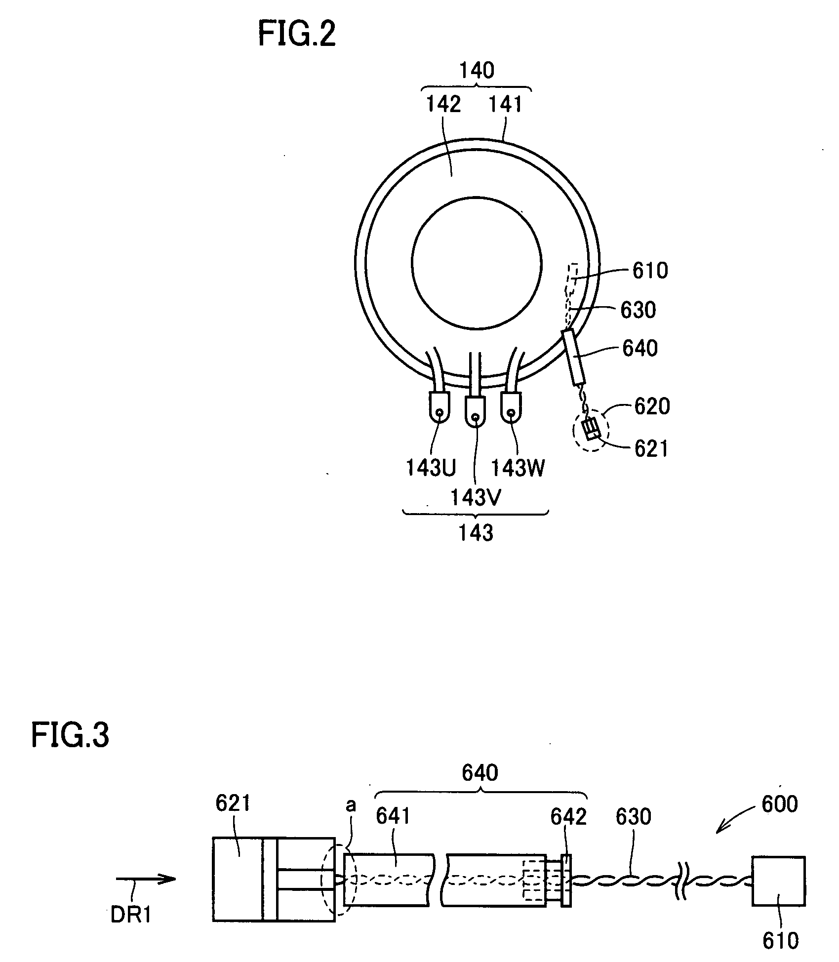
[0069]FIG. 3 is a view showing temperature detector 600 in accordance with the first embodiment of the present invention. Referring to FIG. 3, temperature detector 600 in accordance with the present embodiment includes thermistor 610, connector 621, lead wire 630, and varnish transfer suppressing portion 640. A connector of connection wiring (connection wiring 2A from ECU 2) is fitted into connector 621 from the direction of arrow DR1. Here, varnish transfer suppressing portion 640 has a protection tube 641 and a grommet 642.
[0070]Protection tube 641 is provided to surround lead wire 630 and prevents a damage on the insulating coating portion of lead wire 630. A material having relatively high oil-resistance and heat-resistance is used as protection tube 641. Grommet 642 is an electrical part generally widely used to seal the end portion of protection tube 641 on the thermistor 610 side. Thus, it is suppressed that varnish moving on the surface of lead wire 630 flows into protection...
second embodiment
[0086]FIG. 9 is a view showing temperature detector 600 in accordance with the second embodiment. Referring to FIG. 9, temperature detector 600 in accordance with the present embodiment is a modification of the temperature detector in accordance with the first embodiment and is characterized in that transfer suppressing portion 640 has protection tube 641 and a heat-shrinkable tube 643. In other words, in the present embodiment, heat-shrinkable tube 643 forms “seal portion”.
[0087]Heat-shrinkable tube 643 seals the end portion of protection tube 641 on the thermistor 610 side. Thus, it is suppressed that varnish moving on the surface of lead wire 630 flows into protection tube 641. As a result, intrusion of varnish into connector 621 is prevented.
[0088]In this manner, also in the present embodiment, similarly to the first embodiment, intrusion of varnish into the connector can be suppressed with a simple structure.
third embodiment
[0089]FIG. 10 is a view showing temperature detector 600 in accordance with the third embodiment. Referring to FIG. 10, temperature detector 600 in accordance with the present embodiment is a modification of the temperature detector in accordance with the first and second embodiments and is characterized in that transfer suppressing portion 640 has protection tube 641 and a seal agent 644. In other words, in the present embodiment, seal agent 644 forms “seal portion”.
[0090]Seal agent 644 is configured to include, for example, liquid gasket (FIPG: Formed In Place Gasket), silicone rubber, resin, or the like, and seals the end portion of protection tube 641 on the thermistor 610 side. Thus, it is suppressed that varnish moving on the surface of lead wire 630 flows into protection tube 641. As a result, intrusion of varnish into connector 621 is prevented.
[0091]FIG. 11, FIG. 12 are views illustrating a fabrication process of the temperature detector in accordance with the present embod...
PUM
 Abstract
Description
Claims
Application Information