Shield connector and shielded cable with connector

a shielding connector and shielding cable technology, which is applied in the direction of coaxial cables/analogue cables, coaxial device connections, cables, etc., can solve the problems of inability to effectively suppress electromagnetic noise intrusion and leakage, and inability to ensure sufficient shielding properties. , to achieve the effect of preventing excessive deformation of the end part of the shield conductor by crimping, excellent shielding properties, and effective suppression of electromagnetic nois

Active Publication Date: 2019-08-13
AUTONETWORKS TECH LTD +2
View PDF23 Cites 5 Cited by
  • Summary
  • Abstract
  • Description
  • Claims
  • Application Information

AI Technical Summary

Benefits of technology

[0011]According to the above-described shield connector, the base and the cover of the shield shell respectively include the base-side plates and the cover-side plates. Additionally, the cover-side plates overlap with the base-side plates to cover the engaging hole of the base-side plate. Further, the base (bottom plate and base-side plates) and the cover (upper plate and cover-side plates) are formed continuously from the inner housing toward the cable inserting portion. Thus, a clearance is unlikely to be formed in a circumferential direction of the shield shell, and the inner housing and the exposed end parts of the wires are covered around the entire circumference by the shield shell. Therefore, the shield connector can effectively suppress the intrusion and leakage of electromagnetic noise and is excellent in shielding properties.
[0012]The inner housing can be positioned and fixed to the base by the engagement of the convex portion of the inner housing and the engaging hole of the base-side plate. Thus, the shield connector can be assembled easily.
[0013]The base may include a projection projecting from an outer surface of the base-side plate and a fitting hole may be formed in the cover-side plate of the cover. The projection of the base may be fit into the fitting hole. Accordingly, the cover can be positioned and fit to the base by fitting the projection of the base-side plate and the fitting hole of the cover-side plate. Therefore, the shield connector is assembled easily. Further, by providing the base-side plate with the projection and the cover-side plate with the fitting hole, the fit state of the projection and the fitting hole can be confirmed visually from the outside of the shield shell when the base and the cover are fit to assemble the shield shell.
[0014]The cable inserting portion of one of the base and the cover may include a barrel projecting toward the shielded cable and including a crimping piece to be crimped to an end part of the shield connector. The other cable inserting portion may include a projecting piece formed to face the barrel and to contact the end part of the shield connector by being pressed by the crimping piece. In this way, a fastening force can be dispersed when the crimping piece is crimped and the shield connector can be connected more firmly to the end part of the shielded cable while excessive deformation of the end part of the shield conductor by crimping can be prevented. Thus, the above-described embodiment ensures sufficient pull-out strength of the shielded cable.
[0015]The cover may include a ridge projecting from an inner surface of the cover-side plate and extending in a vertical direction, and a vertical groove may be formed in the side surface of the inner housing. The ridge of the cover may be inserted into the vertical groove. According to this above embodiment, the cover can be positioned with respect to the inner housing and the inner housing and the shield shell (base and cover) can be positioned more accurately by inserting the ridge of the cover-side plate into the vertical groove of the inner housing.
[0016]A shielded cable with connector of the present disclosure includes a shielded cable with wires including at least one communication wire and a shield conductor for collectively covering the wires, and the above-described shield connector to be connected to an end part of the shielded cable. According to the above-described shielded cable with connector, the inner housing and the exposed end parts of the wires can be covered around the entire circumference by the shield shell at the end part of the shielded cable. Thus, the above-described shielded cable with connector can effectively suppress the intrusion and leakage of electromagnetic noise in the shield connector and has high shielding properties in the shield connector.

Problems solved by technology

Thus, there is a high possibility that the inner housing and the exposed end parts of the wires cannot be covered around the entire circumference by the shield shell, and it may not be possible to ensure sufficient shielding properties.
Particularly, if the shielded cable includes a communication wire for high-speed communication, the communication wire for high-speed communication easily is affected by electromagnetic noise.
Communication quality deteriorates if shielding properties in the shield connector are low.
Therefore, clearances are formed in the circumferential direction of the shield shell, leading to reduced shielding properties.

Method used


Image

  • Shield connector and shielded cable with connector
  • Shield connector and shielded cable with connector
  • Shield connector and shielded cable with connector

Examples


Embodiment Construction

[0026]Specific examples of a shield connector and a shielded cable with connector according to an embodiment of the present invention are described with reference to the drawings below. The same components are denoted by the same reference signs in the drawings. Note that the present invention is not limited to these illustrations and is intended to be defined by appended claims and include all modifications within the meaning and scope of the appended claims and equivalents.

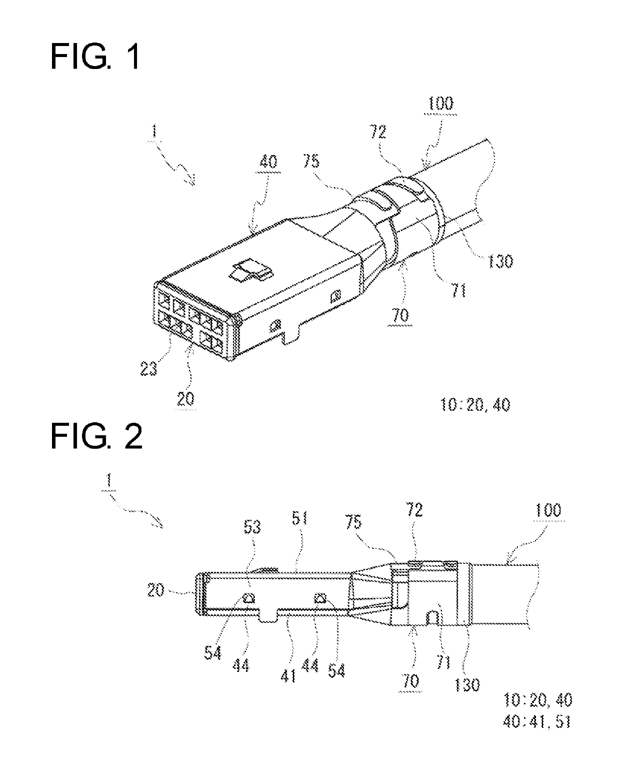
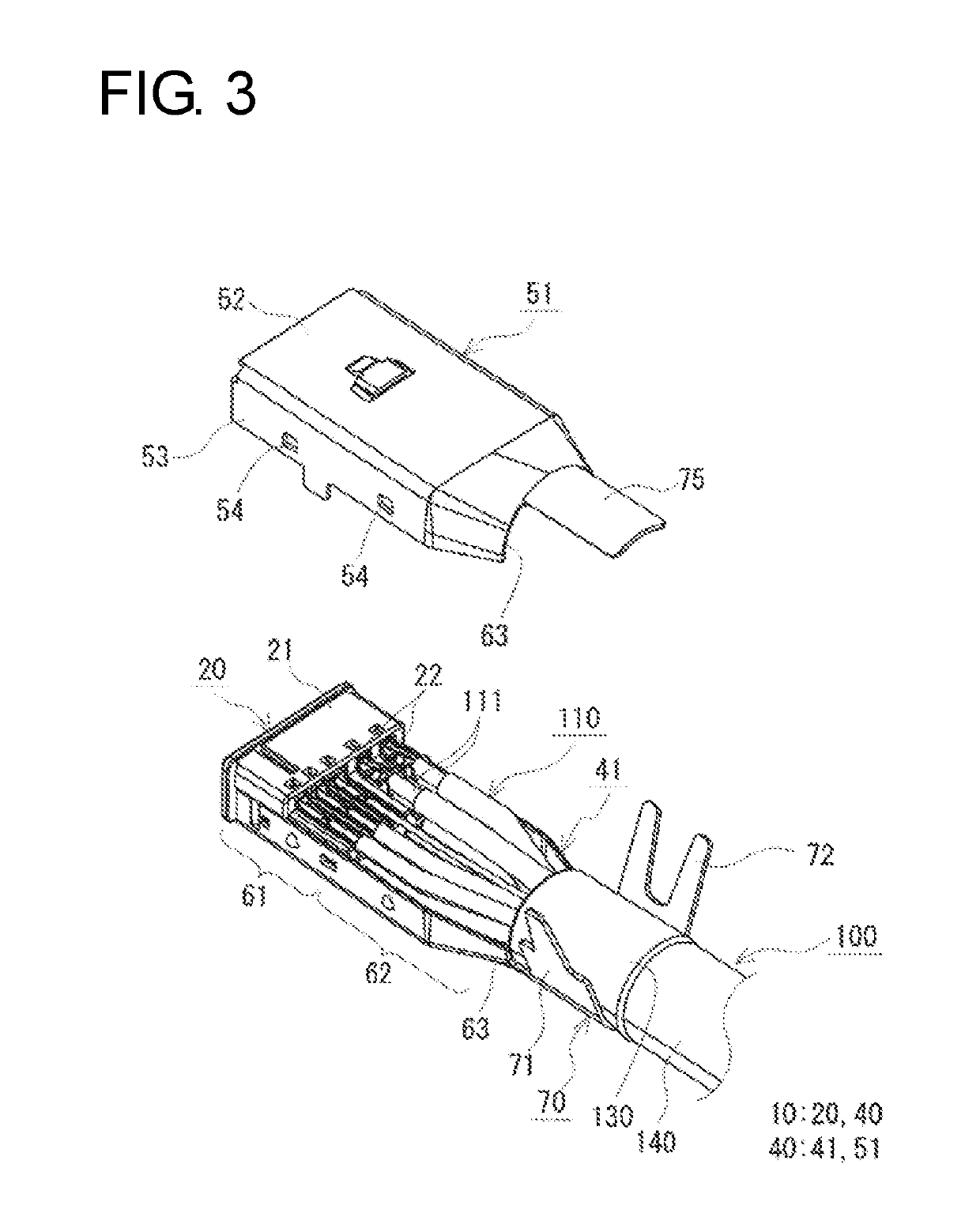
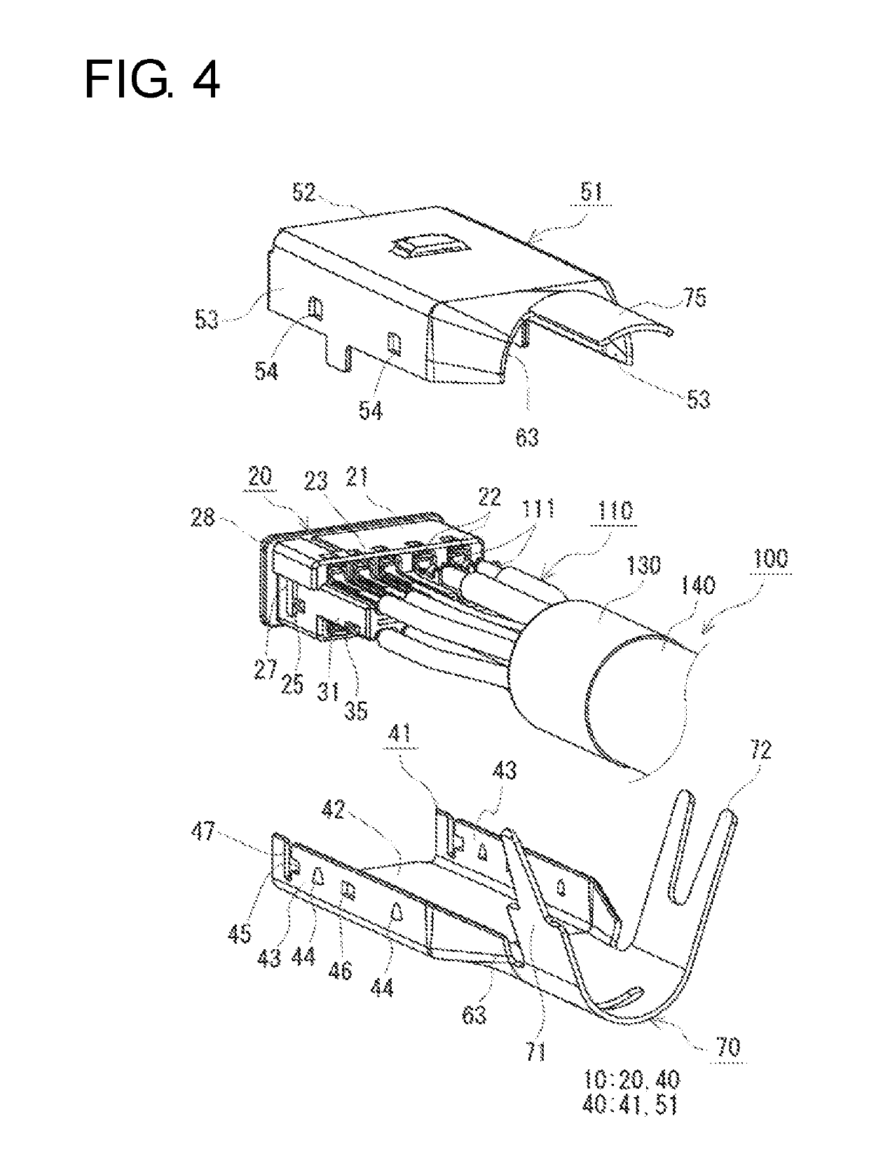
[0027]With reference to FIGS. 1 to 9, an overview of a shield connector and a shielded cable with connector of one embodiment is described. The shielded cable with connector 1 of the embodiment includes a shielded cable 100 and a shield connector 10 to be connected to an end part of the shielded cable 100, as shown in FIGS. 1 and 2. The shield connector 10 includes an inner housing 20 and a shield shell 40, as shown in FIGS. 3 and 4. The shield shell 40 includes a base 41, on which the inner housing 20 is arrang...


PUM

PropertyMeasurementUnit
electricallyaaaaaaaaaa
shapeaaaaaaaaaa
shielding propertiesaaaaaaaaaa

Abstract

A shield connector includes an inner housing that hold terminals connected to wires, and a shield shell accommodates an inner housing and an end of the shielded cable. The shield shell includes a cable inserting portion to receive the shielded cable. A convex portion projects from a side of the inner housing. The shield shell includes a base on which the inner housing is arranged, and a cover fit to the base. The base includes a bottom plate to cover a bottom of the inner housing, two base-side plates to cover side surfaces of the inner housing, and an engaging hole in the base-side plate. The convex portion of the inner housing engages the engaging hole. The cover includes an upper plate to cover a top of the inner housing, and cover-side plates rising from sides of the upper plate to overlap the base-side plates and cover the engaging hole.

Description

CROSS REFERENCE TO RELATED APPLICATION[0001]The application claims priority based on Japanese Patent Application No. 2015-229222 filed on Nov. 24, 2015, the entire disclosure of which is incorporated herein.BACKGROUNDField of the Invention[0002]The invention relates to a shield connector and a shielded cable with connector.Description of the Related Art[0003]Conventionally, a shielded cable is utilized in communication between an electrical component (navigation device, ETC (Electronic Toll Collection) device, monitor or the like) installed in a vehicle, such as an automotive vehicle, and an external device (camera or the like) or between electrical components. A shielded cable for communication generally has wires including a communication wire, a shield conductor for collectively covering the wires and a sheath for covering the outer periphery of the shield conductor. The wire includes a conductor and an insulation coating provided on the outer periphery of the conductor.[0004]Nor...

Claims


Application Information

Patent Timeline
Patent Type & Authority Patents(United States)
IPC IPC(8): H01R4/18H01R13/6581H01B11/18H01R13/6593
CPCH01R13/6593H01R13/6581H01R4/184H01B11/1895
Inventor MAESOBA, HIROYOSHIICHIO, TOSHIFUMI
Owner AUTONETWORKS TECH LTD
Why Eureka
Try Eureka