Trailing edge slit cooling structure and method applicable to turbine blade, turbine blade

A technology of turbine blades and cooling structures, which is applied to the supporting elements of blades, engine manufacturing, machines/engines, etc., can solve the problems of reducing the performance of turbine engines, increasing the weight of blades, and increasing the temperature of the split wall surface, so as to improve the cooling performance and Thermal protection, uniform cooling performance, improved thermal efficiency

Active Publication Date: 2021-12-24
SHANGHAI JIAOTONG UNIV
View PDF6 Cites 0 Cited by
  • Summary
  • Abstract
  • Description
  • Claims
  • Application Information

AI Technical Summary

Problems solved by technology

Although this prior art can form a uniform cooling air film on the surface of the blade during initial cooling, the flow of the air film on the surface of the trailing edge slit will still be easily disturbed by the shear flow and eddy current as it is used, resulting in obvious Flow separation leads to a decrease in the air film cooling performance on the surface of the slit, which increases the temperature of the slit wall and causes ablation, shortening the working life of the turbine blades
In addition, in this solution, ribs are arranged on the split surface of the trailing edge, which increases the weight of the blade and also increases the aerodynamic loss of the external mainstream of the blade, which will reduce the performance of the turbine engine

Method used


Image

  • Trailing edge slit cooling structure and method applicable to turbine blade, turbine blade
  • Trailing edge slit cooling structure and method applicable to turbine blade, turbine blade
  • Trailing edge slit cooling structure and method applicable to turbine blade, turbine blade

Examples


Embodiment Construction

[0038] The present invention will be described in detail below in conjunction with specific embodiments. The following examples will help those skilled in the art to further understand the present invention, but do not limit the present invention in any form. It should be noted that those skilled in the art can make several changes and improvements without departing from the concept of the present invention. These all belong to the protection scope of the present invention.

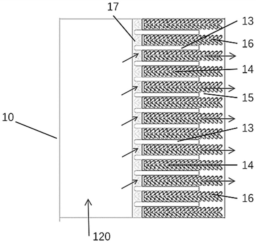
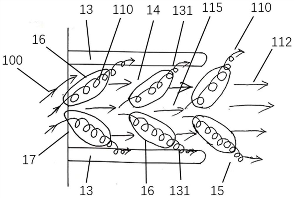
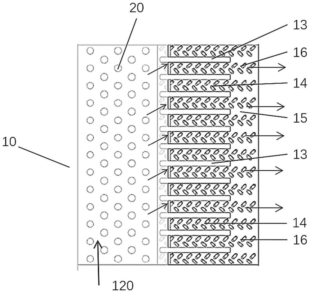
[0039] Such as Figure 1-3 As shown, the present invention provides a cooling structure suitable for turbine blade trailing edge slits, including partition ribs 13, partition rib edges 131, blade trailing edge slits 14, partition rib tails 15, wall depressions 16, and slit inlets 17 , buffer flow channel 112 and intermediate flow channel 115.

[0040] Wherein, the partition rib 13 is arranged on the wall surface of the blade trailing edge split 14; the space between two partition ribs 13 forms the blad...


PUM


Abstract

The invention provides a trailing edge split cooling structure suitable for turbine blades, comprising a partition rib, a blade trailing edge split and a wall surface depression group, wherein the partition ribs are arranged on the wall surface of the blade trailing edge split; two partition ribs The space between forms the blade trailing edge slit; the wall surface of the blade trailing edge slit is arranged with a wall surface depression group; the wall surface depression group includes a plurality of wall surface depressions, the wall surface depression group includes a plurality of wall surface depressions, and the extension direction of at least one wall surface depression Form an inclined angle with the partition rib; and / or, the extension direction of at least one wall surface recess forms an inclined angle with the other side of the partition rib; when the cold airflow enters the trailing edge of the turbine blade, it flows through the wall surface depression along the cold air flow direction through the pin fin A helical vortex is generated which is directed to the partition ribs on both sides. The invention can enhance the cooling performance of the trailing edge slit of the turbine blade and improve the external air film cooling performance by arranging the wall surface depression on the blade trailing edge slit, and is beneficial to reduce the consumption of tail cooling air.

Description

technical field [0001] The invention relates to the technical field of turbine blade cooling, in particular to a trailing edge slit cooling structure and method suitable for a turbine blade, and a turbine blade. Background technique [0002] The trailing edge of the turbine blade of the existing aero-engine and gas turbine adopts a split-jet air-film cooling structure. The cooling channel inside the trailing edge of the turbine blade is composed of the pressure side wall and the suction side wall of the turbine blade, as well as the partition rib, and the partition rib is the extension of the pressure side wall on the split wall of the trailing edge. [0003] The slit at the trailing edge of the turbine blade is a difficult part to cool. Since the design of the turbine blade requires high aerodynamic efficiency, the trailing edge of the turbine blade must be very thin, which makes it difficult to arrange a complex internal cooling structure inside the narrow tail of the turb...

Claims


Application Information

Patent Timeline
Patent Type & Authority Patents(China)
IPC IPC(8): F01D5/18
CPCF01D5/18F01D5/186F05D2220/32F01D5/187F05D2240/304F05D2260/22141F05D2250/24F05D2250/22F05D2250/314F05D2240/30F05D2260/202
Inventor 饶宇刘宇阳张鹏陈诗佳
Owner SHANGHAI JIAOTONG UNIV
Why Eureka
Try Eureka