
Power storage device and method of manufacturing the same

Active Publication Date: 2020-10-01
MURATA MFG CO LTD
View PDF0 Cites 0 Cited by
  • Summary
  • Abstract
  • Description
  • Claims
  • Application Information

AI Technical Summary

Benefits of technology

The present invention provides a power storage device that prevents water from entering the battery. This is achieved by using a polymer compound that is cross-linked in the separator layer, which increases the viscosity of the electrolytic solution in the active material layers. This reduces the diffusion rate of water and prevents it from entering the battery. The method of manufacturing this device can be efficient and reliable. Additionally, a power storage device without the crosslinking initiator can be produced for improved reliability.

Problems solved by technology

This may degrade the characteristics of the power storage device.

Method used


Image

  • Power storage device and method of manufacturing the same
  • Power storage device and method of manufacturing the same
  • Power storage device and method of manufacturing the same

Examples


first embodiment

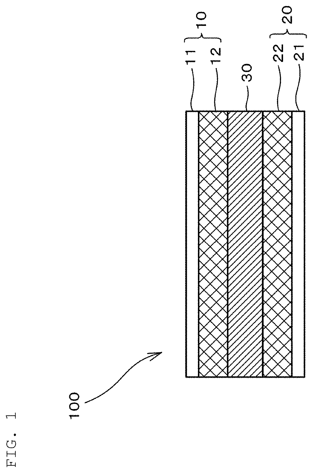
[0029]FIG. 1 is a sectional view illustrating a configuration of a power storage device 100 according to a first embodiment. The power storage device 100 according to the first embodiment includes a positive electrode 10, a negative electrode 20, and a separator layer 30.

[0030]The positive electrode 10 includes a positive electrode current collector 11 and a positive electrode active material layer 12. As the positive electrode current collector 11, for example, aluminum can be used.

[0031]The positive electrode active material layer 12 is formed on one main surface of the positive electrode current collector 11, and includes activated carbon as a positive electrode active material, an electrolytic solution, a first polymer compound that is not crosslinked, a binder, and a crosslinking initiator.

[0032]The binder includes a second polymer compound. As the second polymer compound, for example, carboxymethyl cellulose (CMC) can be used. Further, as the crosslinking initiator, for exampl...

second embodiment

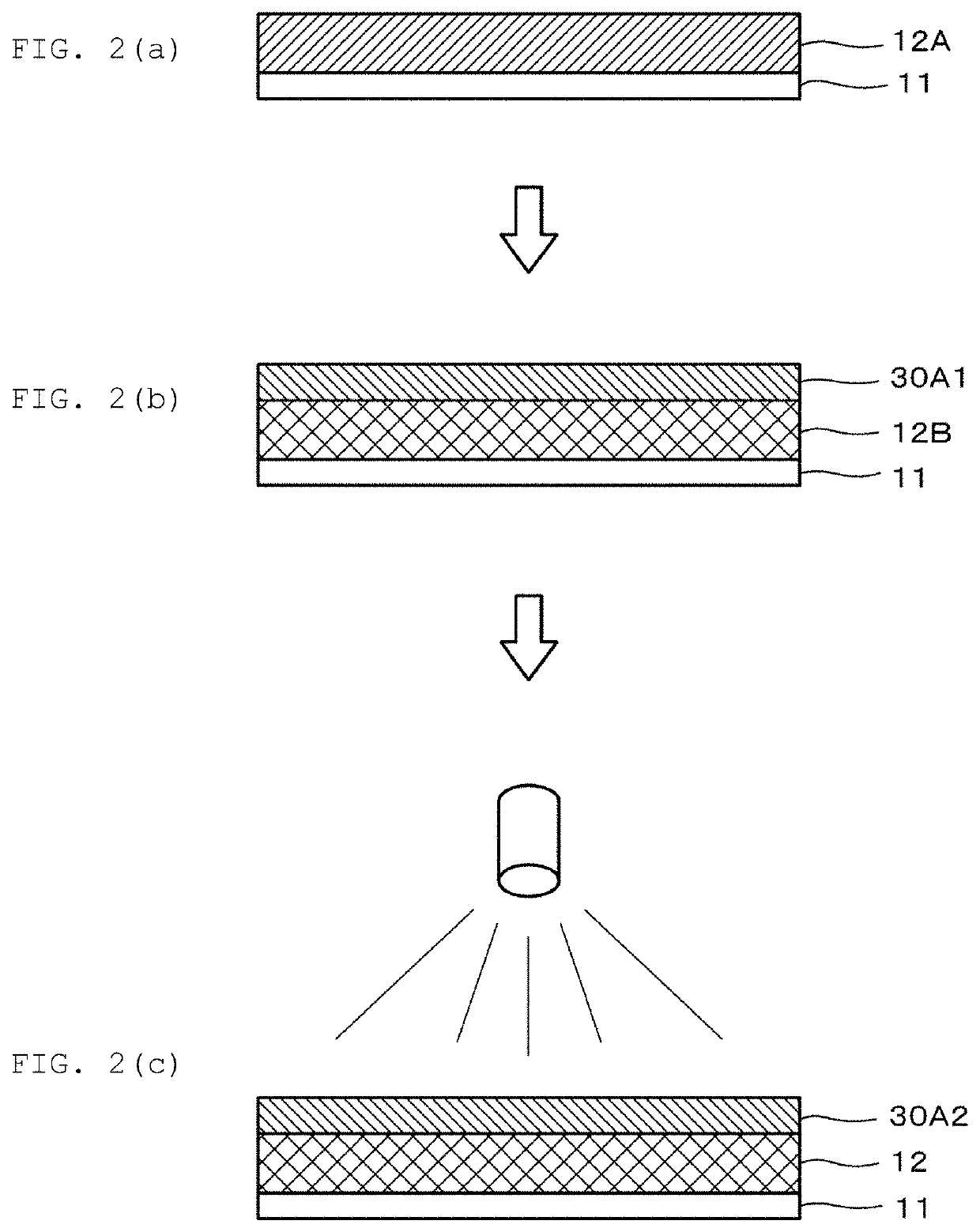
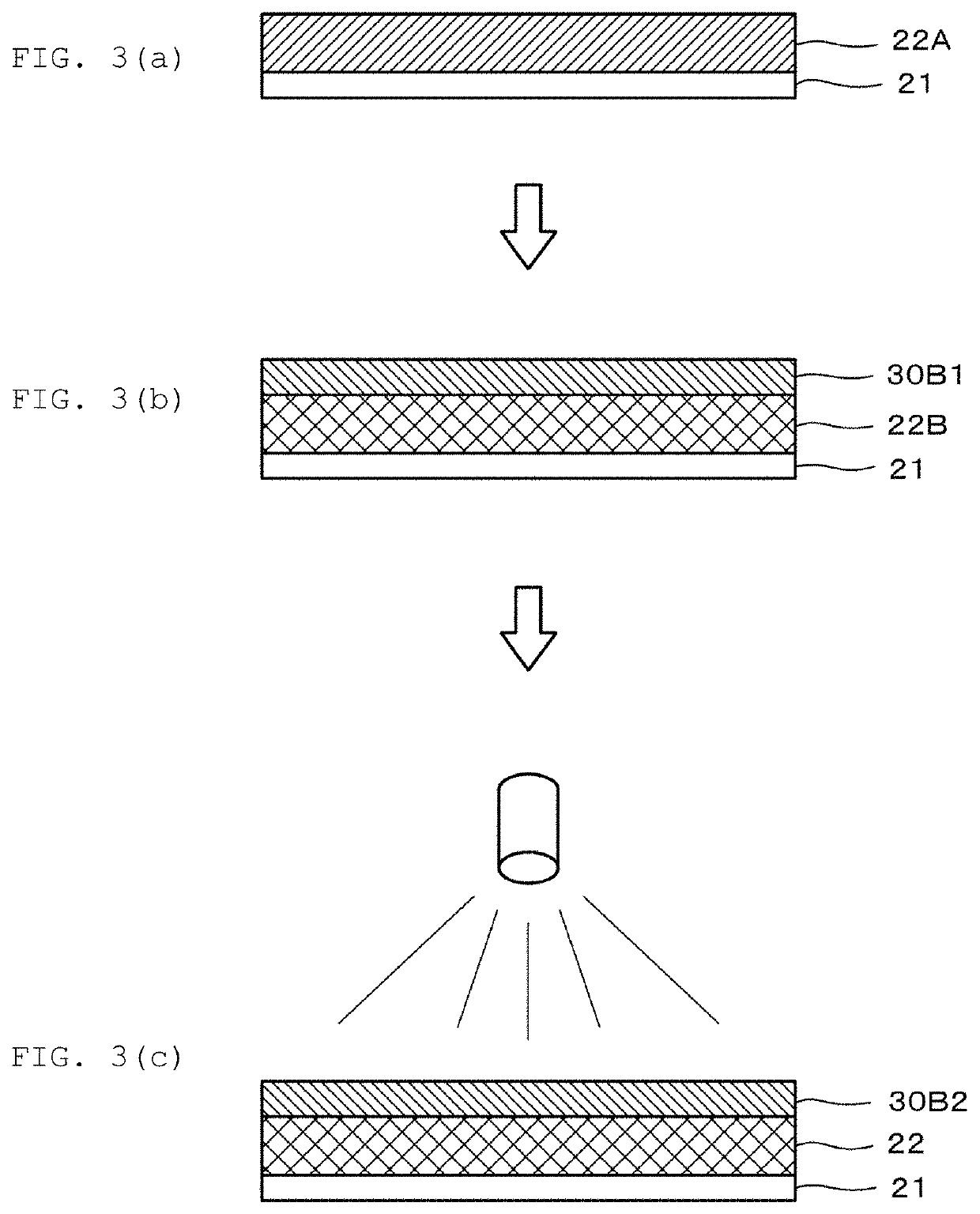
[0062]In the power storage device 100 according to the first embodiment, the positive electrode active material layer 12 and the negative electrode active material layer 22 include a crosslinking initiator. Thus, by irradiating the ultraviolet rays, the positive electrode 10 and a part of the separator layer 30 can be simultaneously manufactured, and the negative electrode 20 and a part of the separator layer 30 can be simultaneously prepared.

[0063]On the other hand, in the power storage device 100 according to a second embodiment, the positive electrode active material layer 12 and the negative electrode active material layer 22 do not include the crosslinking initiator.

[0064]A method of manufacturing the power storage device 100 according to the second embodiment will be briefly described below.

[0065]First, a material obtained by mixing a positive electrode active material, a binder, an electrolytic solution, and a third polymer compound that is not crosslinked is applied onto an ...


PUM


Abstract

A power storage device having a positive electrode including a positive electrode current collector and a positive electrode active material layer, a negative electrode including a negative electrode current collector and a negative electrode active material layer, and a separator layer between the positive electrode and the negative electrode and including a gel electrolyte. At least one of the positive electrode active material layer and the negative electrode active material layer includes an electrode active material, an electrolytic solution, a first polymer compound that is not crosslinked, and a binder having a second polymer compound different from the first polymer compound.

Description

CROSS REFERENCE TO RELATED APPLICATIONS[0001]The present application is a continuation of International application No. PCT / JP2018 / 044219, filed Nov. 30, 2018, which claims priority to Japanese Patent Application No. 2018-004962, filed Jan. 16, 2018, the entire contents of each of which are incorporated herein by reference.FIELD OF THE INVENTION[0002]The present invention relates to a power storage device and a method of manufacturing the same.BACKGROUND OF THE INVENTION[0003]A known power storage device has a configuration in which a separator is provided between a positive electrode and a negative electrode.[0004]As one of such power storage devices, Patent Document 1 discloses an electric double layer capacitor provided with a polarizable electrode including a gel polymer compound including an electrolytic solution. Further, Patent Document 2 discloses an electrochemical capacitor provided with an electrode including an ionic liquid and a gel polymer compound.[0005]Patent Documen...

Claims


Application Information

Patent Timeline
IPC IPC(8): H01G11/28H01G11/30H01G11/86H01G11/56
CPCH01G11/30H01G11/56H01G11/28H01G11/86H01G11/38H01G11/64
Inventor MANO, KYOTAROKIMURA, KENJIFUKUDA, YASUTAKEUEDA, YASUHIKO
Owner MURATA MFG CO LTD
Features
  • Generate Ideas
  • Intellectual Property
  • Life Sciences
  • Materials
  • Tech Scout
  • Unparalleled Data Quality
  • Higher Quality Content
  • 60% Fewer Hallucinations
Learn More