Eureka AIR delivers breakthrough ideas for toughest innovation challenges, trusted by R&D personnel around the world.

Apparatus and Method of Film Formation

Inactive Publication Date: 2009-09-17
ULVAC INC
View PDF6 Cites 0 Cited by
  • Summary
  • Abstract
  • Description
  • Claims
  • Application Information

AI Technical Summary

Benefits of technology

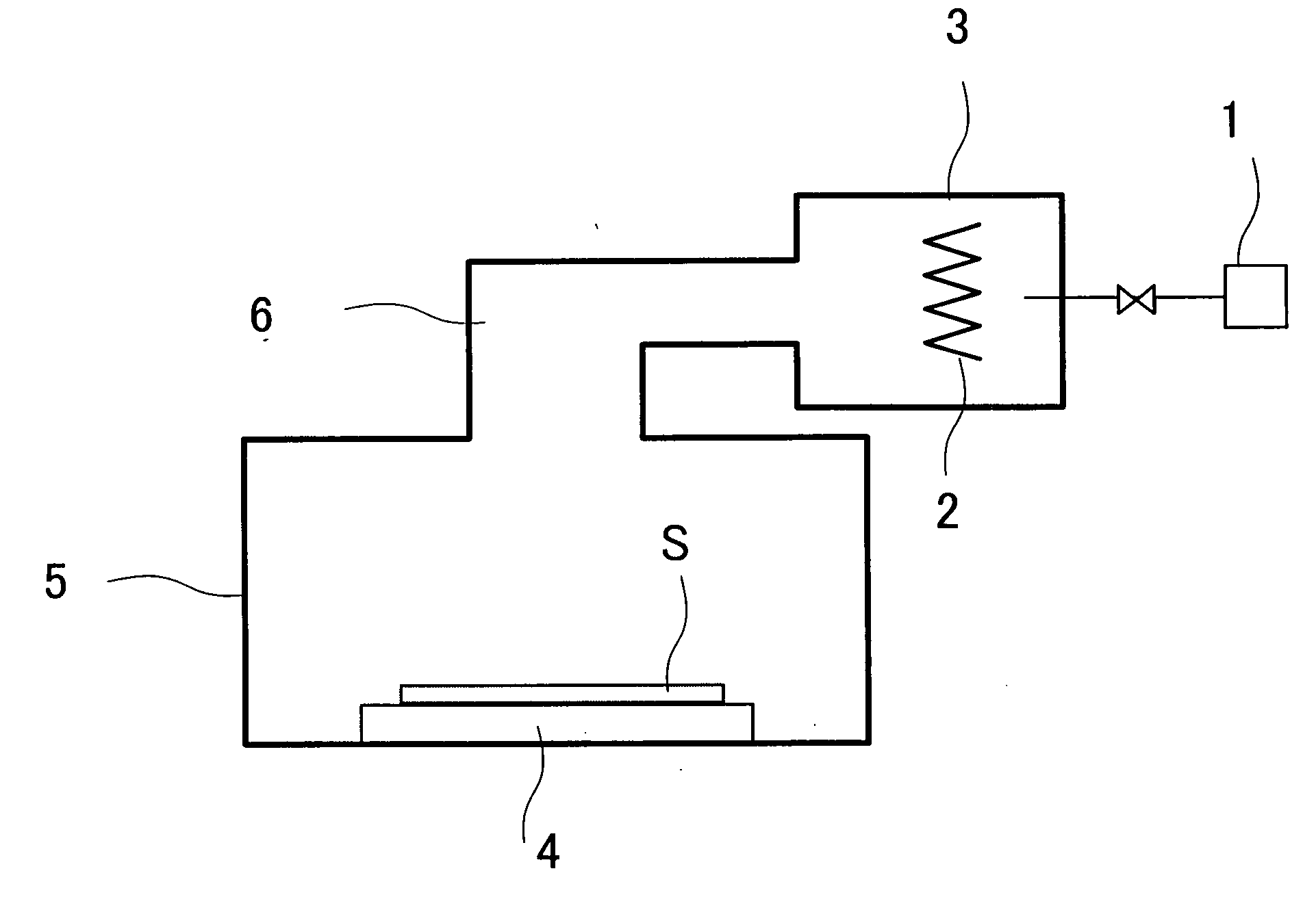
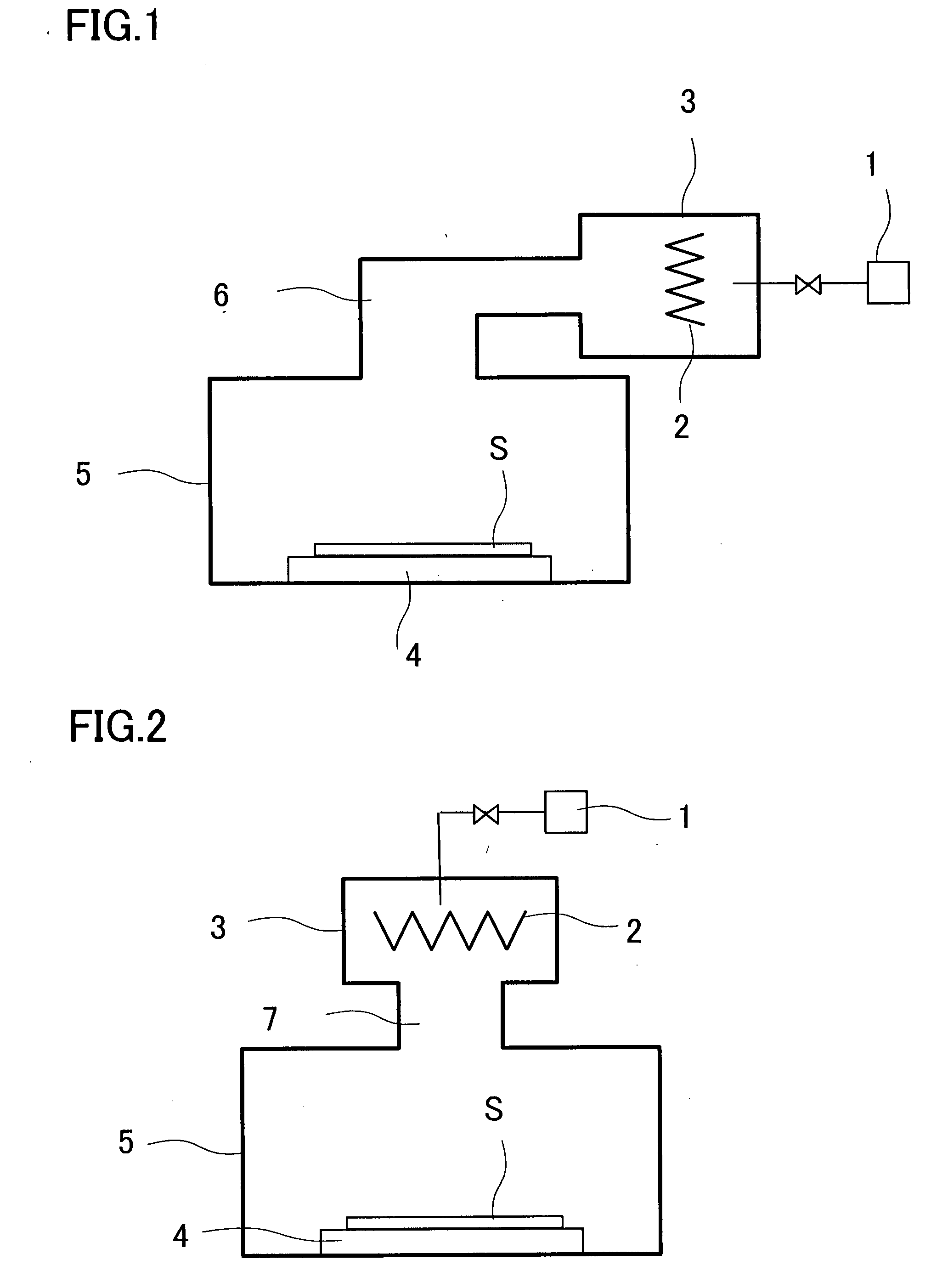
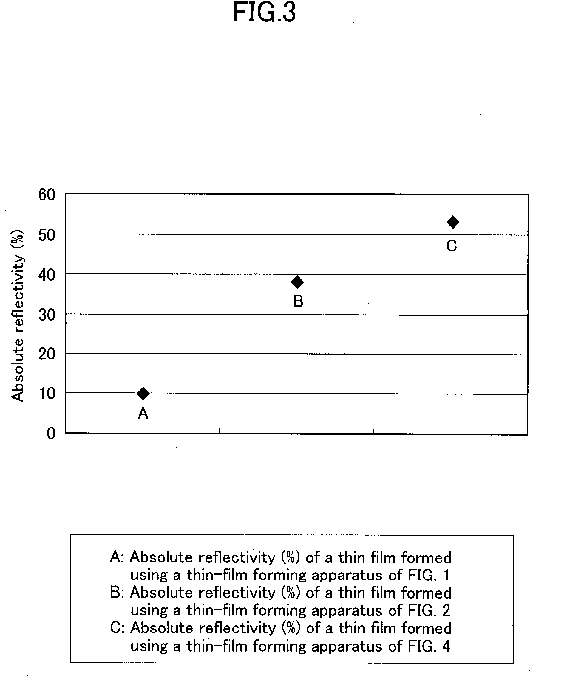
[0030]The film forming apparatus of the present invention has an advantage that the radical produced at the catalyst source can be prevented from being deactivated during the transportation so that the reaction of the radical with the source gas can be more efficiently performed to form a film having the desired properties.

Problems solved by technology

However, if such reactant gases are used, a reaction between the reactant gas and the precursor on the substrate cannot produce sufficiently to form a film having the desired properties.
Therefore, this may form a film containing impurities more or a film having its increased resistivity and also raise another problem in that the adhesion between the formed film and the underlying layer is inferior.
As a result, there is a risk in that the catalyst source reacts with the source gas to form a film of a metal contained in the source gas on the catalyst source.
However, this reduces the efficiency of transportation for the radical.
In other words, the radical deactivates during transportation so that a film having the desired properties cannot be formed.
As a result, the source gas is hard to deposit on the catalyst source.
In such a manner, the prior art could not form the desired film since the radical was deactivated during the transportation so that the amount of radial sufficient to react with the source gas did not reach the substrate.

Method used


Image

  • Apparatus and Method of Film Formation
  • Apparatus and Method of Film Formation
  • Apparatus and Method of Film Formation

Examples


example 1

[0070]The transportation efficiency of radical was checked when the size of opening 47 was changed using the film forming apparatus shown in FIG. 9. The film forming apparatus was provided with the partition member 51 located at the opening 47. By changing the size of this partition member 51 to change the size of the opening 47, the distance y between a point at which the shortest linear line connecting the periphery of the substrate S with the periphery of the opening 47 intersects the catalyst source 48 and the edge of the catalyst source can be changed. The high-melting-point metal wire 81 forming the catalyst source 48 was made of tungsten and had its length z of 100 mm. It is noted that similar parts to those of FIG. 4 have similar reference numerals in FIG. 9.

[0071]When the distance y from the catalyst was changed to 0 mm, 35 mm, 40 mm and 45 mm respectively by changing the size of the partition member 51 in the aforementioned arrangement, the radicals produced for the respec...

example 2

[0076]The transportation efficiency of radical was checked using the film forming apparatus of FIG. 4 having no shower nozzle 443. In this film forming apparatus, the diameter of the opening 47 was equal to the internal diameter of the catalyst chamber 46. Each of 8-inch wafers provided by forming a thermal oxide film and then a copper oxide film thereover was used as a substrate S. The substrate S was placed on the substrate supporting stage 441. The angle ω included between the shortest linear line connecting the periphery of substrate S with the periphery of the opening 47 and the substrate was about 80 degrees.

[0077]The catalyst source 48 was formed by arranging eight high-melting-point metal wires 81 made of tungsten and each having its length of 350 mm and its diameter of 0.5 mm into such an octagonal configuration as shown in FIG. 8, by arranging four high-melting-point metal wires 81 each having its diameter of 0.5 mm and its length of 300 mm into a regular square configurat...

example 3

[0081]By using the film forming apparatus shown in FIG. 4, the properties of the formed films of TaNx were evaluated. Substrates S used were 8-inch wafers identical to those of the example 1.

[0082]First, each of the substrates S was placed on the substrate supporting stage 441 in the film forming chamber 44. The temperature of substrate supporting stage 441 was set at 250 degrees Celsius. After the temperature of the substrate had stabilized, N2 gas as purge gas was introduced into the catalyst chamber 46 in the rate of 200 sccm.

[0083]After five seconds from the introduction of purge gas, TIMATA as source gas was introduced through the shower nozzle 443 in the rate of 0.5 g / min.

[0084]After the precursor of the source gas had been adsorbed by the substrate S, the introduction of source gas was stopped.

[0085]The introduction of purge gas to the catalyst chamber 46 was stopped after few seconds from the stoppage of introduction of the source gas.

[0086]Then, H2 gas, as reactant gas, was...


PUM

PropertyMeasurementUnit
Fractionaaaaaaaaaa
Fractionaaaaaaaaaa
Lengthaaaaaaaaaa

Abstract

In a vacuum chamber 42 comprising a film forming chamber 44 and a catalyst chamber 46 including a catalyst source 48 located opposed to a substrate S, the film forming chamber 44 is connected to the catalyst chamber 46 through an opening 47, the catalyst source being displace at a position satisfying ω≧θ, where ω is an angle included between the shortest linear line connecting the periphery of a substrate on the substrate supporting stage with the periphery of the opening and the substrate and where θ is an angle included between the shortest linear line connecting the periphery of the substrate with the edge of the catalyst source and the substrate. By using such a film forming apparatus, a radical produced at the catalyst source can be prevented from being deactivated so that the reaction between a source gas and the radical will be efficiently performed to form the desired film.

Description

TECHNICAL FIELD[0001]The present invention relates to an apparatus and method of film formation.BACKGROUND ART[0002]In recent years, ALD (Atomic Layer Deposition) method has been focused as a technique of film formation in the field of semiconductor device production.[0003]Usually, ALD forms a desired film by causing the surface of a substrate to adsorb the precursor of a source gas at each atomic layer after the source gas has been introduced into a vacuum chamber (absorption step) and then introducing a reactant gas into the vacuum chamber so that the precursor reacts with the reactant gas on the surface of the substrate in such a state as the precursor of a source gas has been adsorbed onto the surface of the substrate (reaction step). The adsorption step onto which the precursor adsorbed onto the substrate and reaction steps which the precursor react with the reactant gas are repeated many times to form a film having the desired thickness.[0004]ALD uses an ordinary raw gas or a ...

Claims


Application Information

Patent Timeline
IPC IPC(8): C23C16/44C23C16/00
CPCC23C16/34C23C16/452C23C16/44C23C16/52
Inventor GONOHE, NARISHIHARADA, MASAMICHIKATO, NOBUYUKI
Owner ULVAC INC
Why Eureka
Eureka Blog
Learn More