Eureka AIR delivers breakthrough ideas for toughest innovation challenges, trusted by R&D personnel around the world.

Devices and methods for batch processing magnetic bead assays

Active Publication Date: 2012-01-26
CYTIVA SWEDEN AB
View PDF0 Cites 1 Cited by
  • Summary
  • Abstract
  • Description
  • Claims
  • Application Information

AI Technical Summary

Benefits of technology

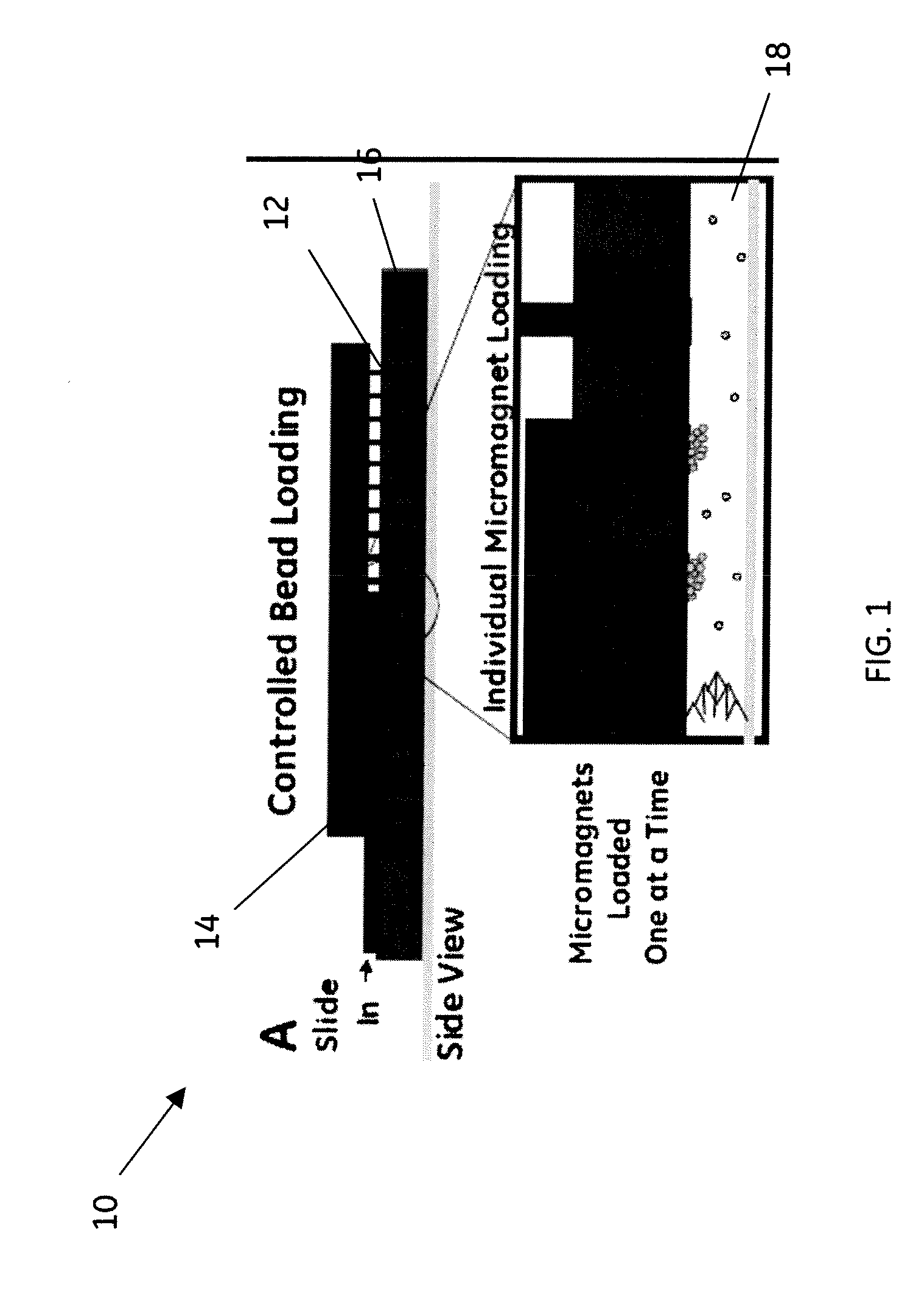
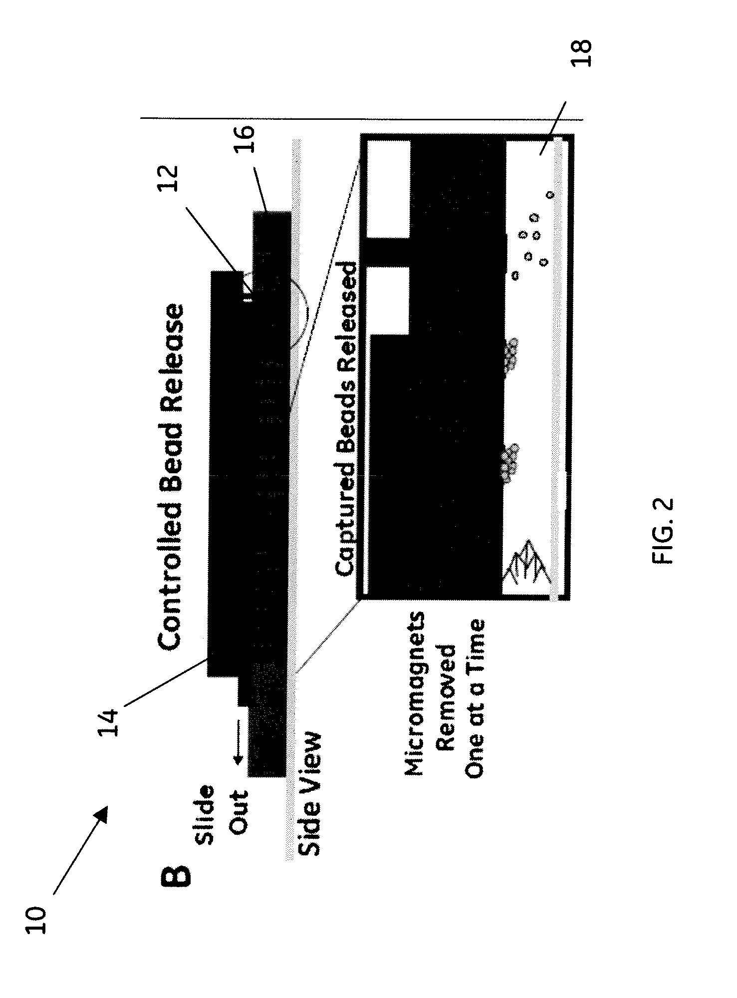
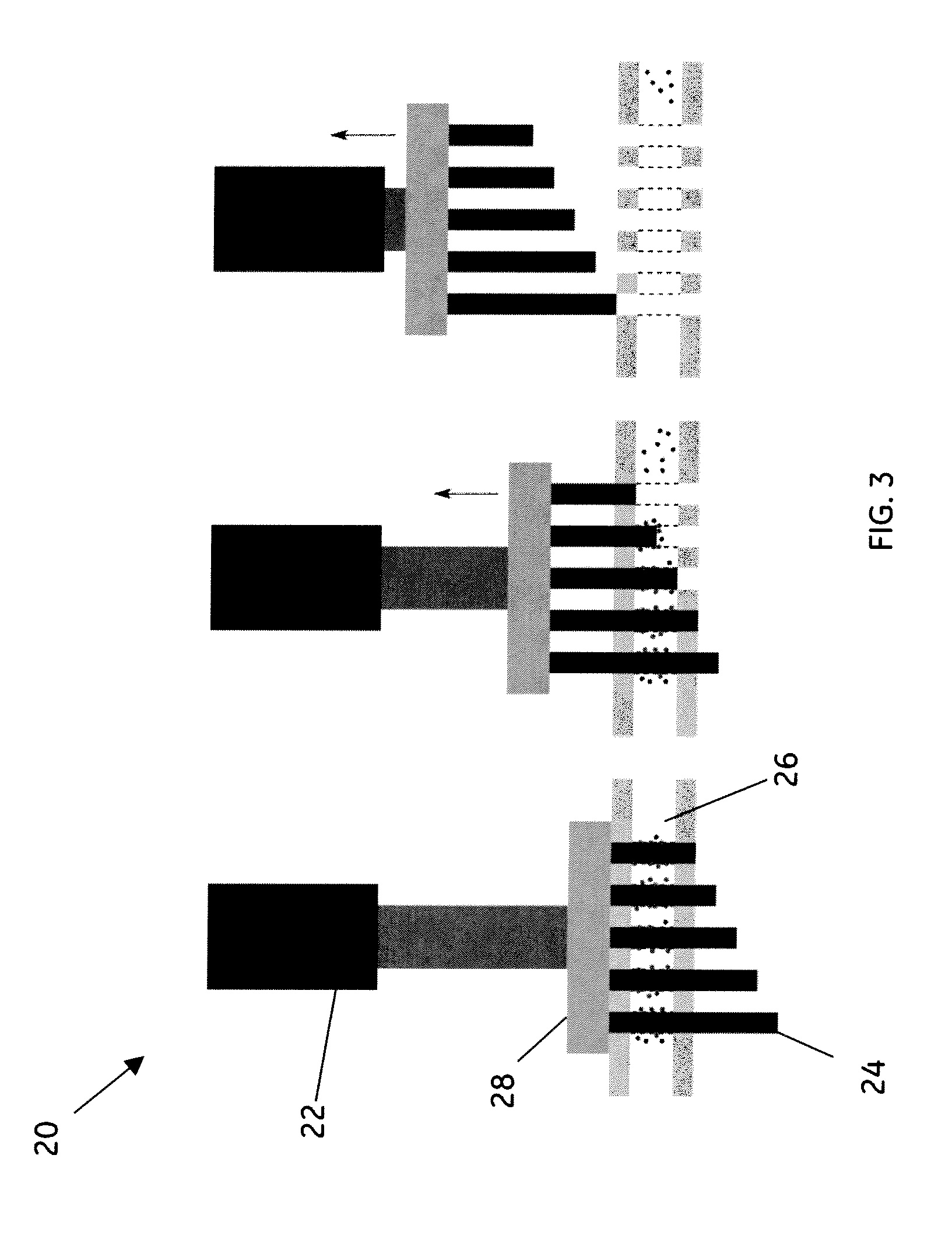
[0007]The arrays and methods of the invention substantially improve the efficiency of magnetic bead assays and provide a platform on which bead reactions may be optimized and batch processed by controlling the bead-to-target ratio and the loading and release of beads in discrete quantities. In one or more examples of the methods of the invention, a batch-mode process is used in which the bead to target ratio is controlled to ensure an efficient reaction. In addition, one or more examples of the methods of the invention may be adapted to process the magnets individually to allow batch processing of the beads post-reaction.

Problems solved by technology

However, sample preparation for these microdevices remains an unmet challenge before such devices are adapted for point-of-care and on-site environments.
However, as with most bulk bead traps, detection limits are set by the reaction kinetics on the bulk surface used to capture beads.
Current magnetic bead assays are inefficient at high bead counts because the beads clump together, which blocks binding sites on the beads.
When performing surface reactions on beads trapped within continuous flow channels, bead clumping during magnetic bead immobilization interferes with surface binding reactions and downstream analysis.
Although others have attempted to trap a small number of beads in parallel microfluidic reaction chambers for better control over bead reactions, this approach requires that the reactions take place in nanoliter-sized compartments, which severely limits throughput.
However, electromagnets are too expensive and require too much power to employ them in magnetic bead assays.
Similarly, passive arrays of permanent magnet elements are not practical for magnetic bead assays because the number of beads, on each magnet surface in a passive array on each individual magnetic surface, cannot be controlled.
In addition, although studies have been conducted on flow cell arrays for capturing rare cells on arrays of immuno-functionalized posts, no methods exist to extend these studies to magnet bead-based approaches.

Method used


Image

  • Devices and methods for batch processing magnetic bead assays
  • Devices and methods for batch processing magnetic bead assays
  • Devices and methods for batch processing magnetic bead assays

Examples


example

[0043]This example of the method uses the embodiment shown in schematic diagram in FIG. 4 comprising a magnetic array integrated into a microfluidic chip 30 that comprises the two microfluidic modules, sample prep module 32 and cytometer module 34. Sample preparation module 32 comprises a fluidic manifold with five, 100 μL capacity reservoirs, each addressable by a valve.

[0044]The active fluidic components used in this example were made using sterolithography. A fluidic control box was used, which, using both positive and negative pressure, was operated using four separate diaphragm pumps and an array of 16 solenoid valves for controlling the pneumatic valve lines. The sandwich-immunoassay was performed using a continuous flow by washing the pre-functionalized and trapped magnetic beads with each reagent. Carboxy-functionalized Luminex ® microspheres (sets 56, 59, 77, 81, 98) were coupled to Goat-IgG, specific for Shigella, Listeria, Salmonella, E. coli, and Campylobacter. After the...


PUM


Abstract

A microfluidic device for batch processing magnetic bead assays and having one or more microfluidic sample channels, comprising, one or more micromagnets seated in a fixture; and an actuator; wherein a portion of each micromagnet is in releasable operative association with one or more of the microfluidic sample channels, and another portion of each micromagnet is in releasable operative association with the actuator; and methods for using the same.

Description

STATEMENT REGARDING FEDERALLY SPONSORED RESEARCH & DEVELOPMENT[0001]This invention was made with Government support under contract number N00173-08-2-C003 that was awarded by the Navel Research Laboratory. The Government has certain rights in the invention.BACKGROUND[0002]The invention relates generally to microflow cytometry and more particularly to devices and methods for batch processing magnetic bead assays.[0003]Flow cytometry is used in broad areas of technologies such as medical diagnostics. Such flow cytometers have generally been located in centralized laboratory settings and run by trained technicians. More recently laboratories are moving towards smaller, less expensive instruments that provide a greater level of automation. Microfluidics has played an important role in this transition, providing simpler methods of sample injection, cell sorting, and optical interrogation. However, sample preparation for these microdevices remains an unmet challenge before such devices ar...

Claims


Application Information

Patent Timeline
IPC IPC(8): C40B30/04C40B60/12
CPCB01L3/502761B01L2200/0621B01L2200/0668B01L2300/0877B01L2400/043G01N33/533B03C1/286B03C2201/18B03C2201/26G01N35/0098B01L3/00B03C1/0332
Inventor SHAIKH, KASHAN ALIPULEO, CHRISTOPHER MICHAELXIE, JUNZENG, HANSONGZHU, LI
Owner CYTIVA SWEDEN AB
Why Eureka
Eureka Blog
Learn More