Endoscope system and method for inspecting electronic endoscope

Inactive Publication Date: 2009-09-17
FUJIFILM CORP
View PDF12 Cites 67 Cited by
  • Summary
  • Abstract
  • Description
  • Claims
  • Application Information

AI Technical Summary

Benefits of technology

[0021]The endoscope system according to the present invention can correctly detect the number of broken optical fibers in the light guide.

Problems solved by technology

Since the optical fibers become rigid with a lapse of time, the optical fibers gradually deteriorate and finally snap due to stress applied in using the electronic endoscope.
Such a flexible tube, however, cannot always prevent the break because the optical fibers necessarily deteriorate with time.
Adjustment by the aperture stop, however, is insufficient in a case where a predetermined number or more of optical fibers have already snapped.
In this case, a shortage of light exiting from the light g

Method used


Image

  • Endoscope system and method for inspecting electronic endoscope
  • Endoscope system and method for inspecting electronic endoscope
  • Endoscope system and method for inspecting electronic endoscope

Examples


Example

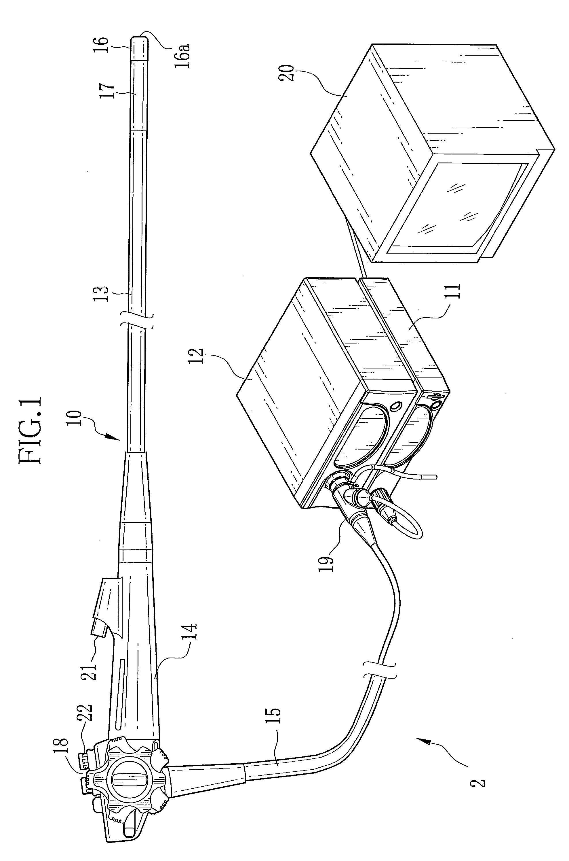
[0033]In FIG. 1, an endoscope system 2 consists of an electronic endoscope 10, a processor device 11, a light source device 12 and a cap 40 (see FIG. 3). The electronic endoscope 10 is provided with a flexible insert section 13 that is introduced into a human body cavity, an operation section 14 that is joined to a base end of the insert section 13, and a universal cord 15 that is connected to the processor 11 and the light source device 12.

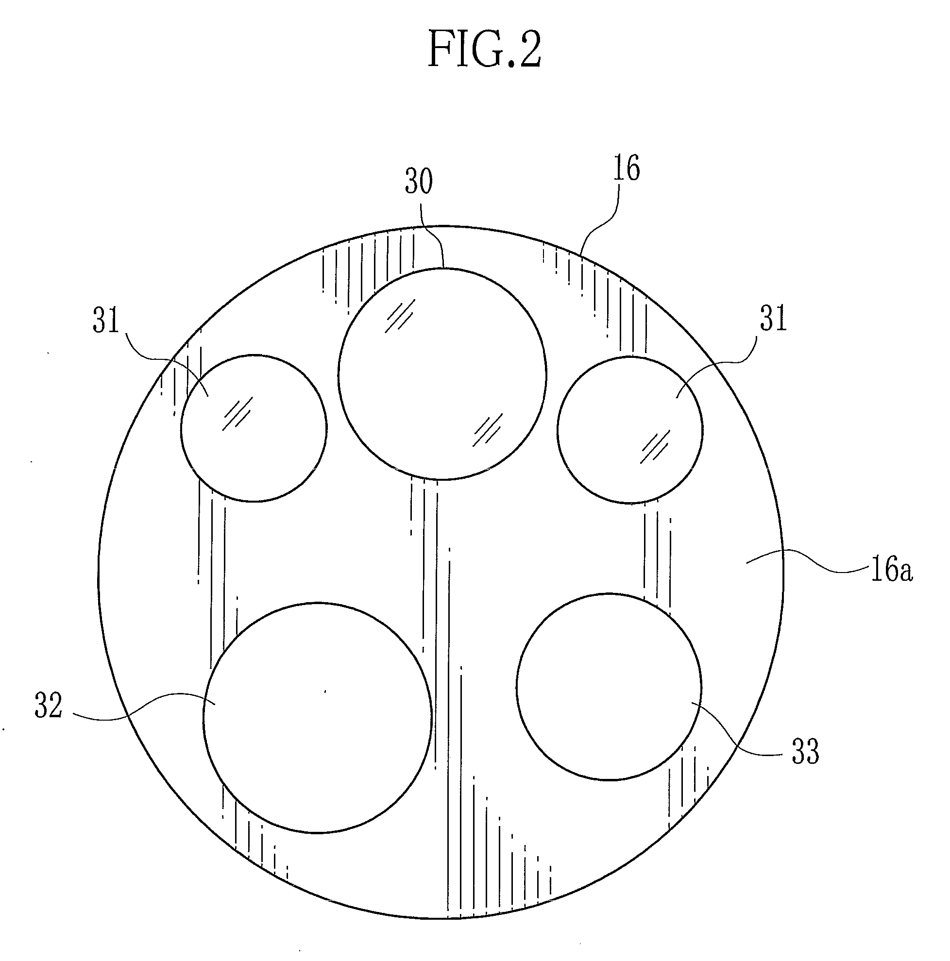
[0034]At an end of the insert section 13 is provided a distal portion 16 that contains a solid-state image sensor (CCD) 50 for capturing an optical image of a target body part to inspect. Behind the distal portion 16, a bending portion 17 consisting of a number of linked ring-like segments is provided. By operating an angle knob 18 on the operation section 14, a number of wires extending in the insert section 13 are pulled and pushed to bend the bending portion 17 from side to side and up and down. Thus, the distal portion 16 is directed to the t...


PUM


Abstract

An electronic endoscope has a light guide for leading a light and a solid-state image sensor for capturing an image of a human body cavity during illumination. In inspecting the number of broken optical fibers in the light guide, a cap is attached to a distal portion of the electronic endoscope. The cap has a test chart. The solid-state image sensor captures an image of the test chart which is illuminated with the light transmitted through the light guide. A photometric circuit calculates an average luminance value “Y” of the test chart from a chart image signal. A broken fiber number calculator calculates the number “N” of broken optical fibers that satisfies N=M×(1−Y/I). “Y” represents an average luminance value of the test chart. “I” represents an ideal average luminance value when all optical fibers are conducting, and “M” represents the total number of the optical fibers.

Description

BACKGROUND OF THE INVENTION[0001]1. Field of the Invention[0002]The present invention relates to an endoscope system that is constituted of an electronic endoscope, a processor device and a light source device, and a method for inspecting the electronic endoscope.[0003]2. Description Related to the Prior Art[0004]An endoscope system is constituted of an electronic endoscope, a processor device and a light source device. The electronic endoscope has a solid-state image sensor at its distal portion for capturing an image of a human body cavity to output an image signal. The processor device receives the image signal from the solid-state image sensor and produces an image to display it on a monitor. The light source device supplies the electronic endoscope with light. Inside the electronic endoscope, a light guide extends. The light from the light source device is led into the distal portion of the electronic endoscope through the light guide, and is incident on the human body cavity f...

Claims


Application Information

Patent Timeline
IPC IPC(8): A61B1/04A61B1/00G01N21/84
CPCA61B1/00165A61B1/05A61B1/042
Inventor ABE, KAZUNORI
Owner FUJIFILM CORP
Why Eureka
Try Eureka