Belt integrated with stress sensing and output reaction

a stress sensing and output reaction technology, applied in the field of belts, can solve the problems of user inability to carry, no wearable tools to help people, and inability to carry, and achieve the effect of improving health status

Inactive Publication Date: 2009-09-17
HUANG JUNG TANG +1
View PDF23 Cites 26 Cited by
  • Summary
  • Abstract
  • Description
  • Claims
  • Application Information

AI Technical Summary

Benefits of technology

[0008]The main objective of this invention is to provide in time and long term monitoring and to provide interactive suggestion t...

Problems solved by technology

Electronic game is a commonly interactive device, and interaction and control can be performed in association with force feedback; however, it does not have training mechanism of physiological function accompanied with breathing, and it is only pure reflective type interaction; moreover, it can not perform activity or health consultation through monitoring way.
Pathological detection device such as blood pressure detector can detect physiological status, but it can not be carried at any time with ease so as to per...

Method used


Image

  • Belt integrated with stress sensing and output reaction
  • Belt integrated with stress sensing and output reaction
  • Belt integrated with stress sensing and output reaction

Examples


embodiment 1

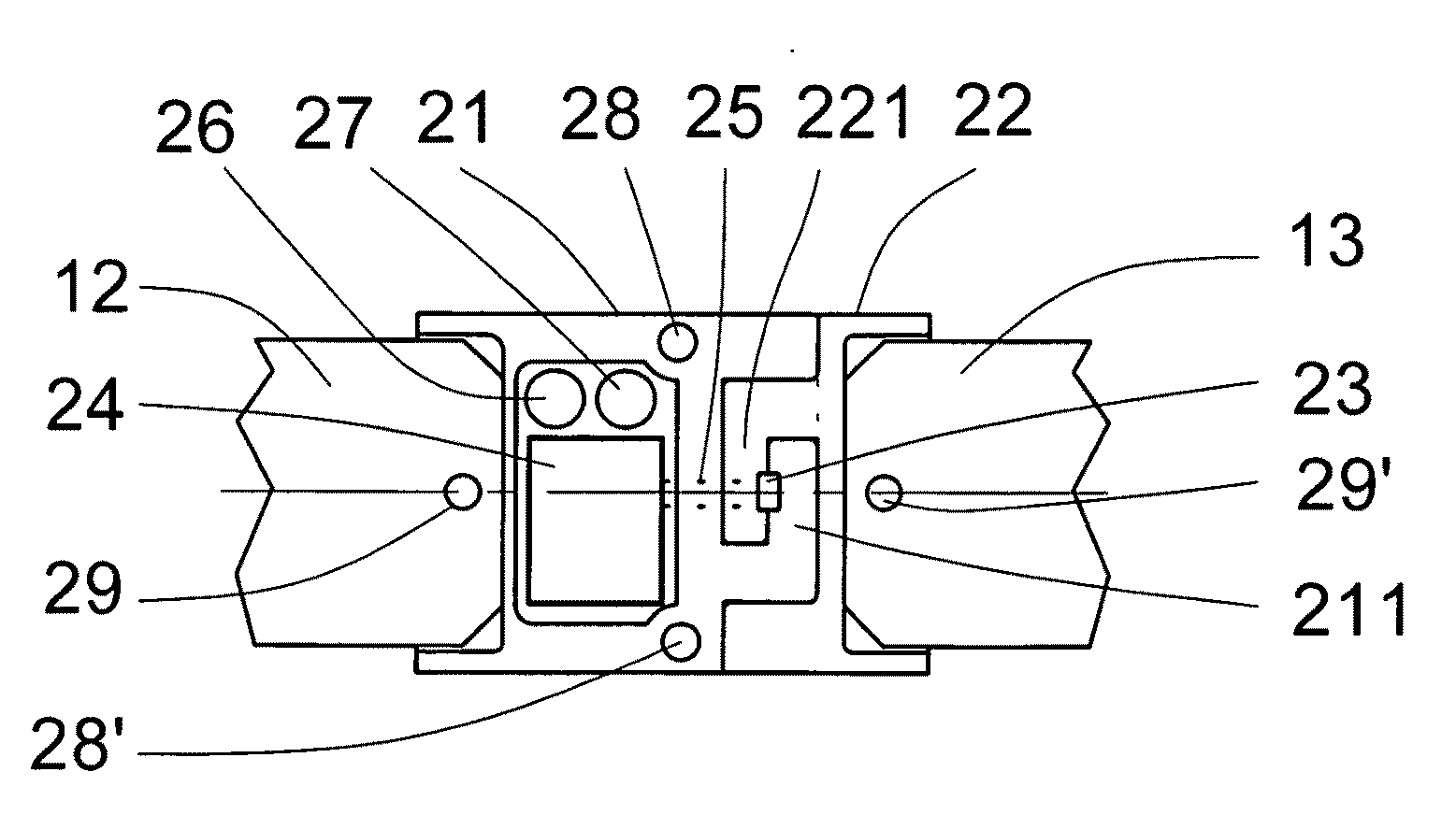
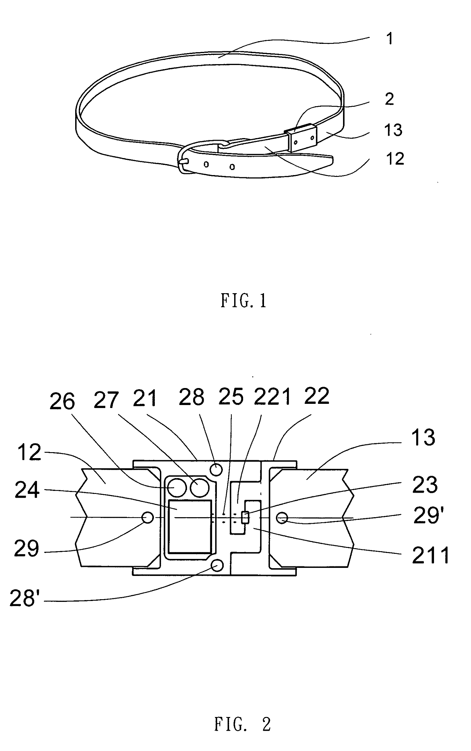
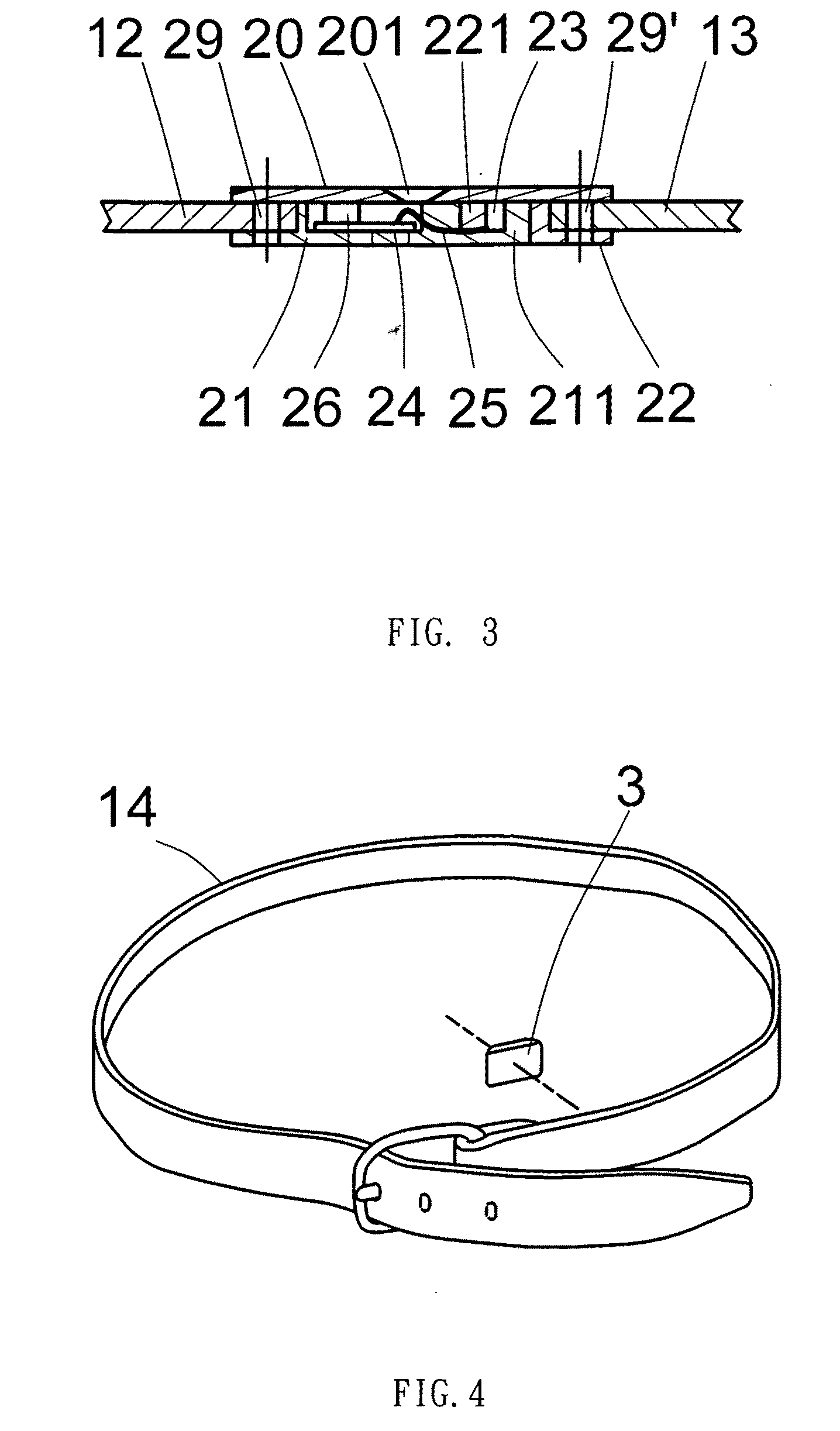
[0025]Referring to FIG. 1 to FIG. 3, this embodiment associates sensor 2 with waist belt 1. Waist belt 1 can be divided into waist belt left end 12 and waist belt right end 13, and sensor 2 is connected to between left and right ends through fixing holes 29 and 29′. Sensor 2 is formed respectively by sensor left component 21, sensor right component 22 and cover plate 20. Moreover, left and right components are hooked to each other by left component tension hook 211 and right component tension hook 221, between, a stress sensor 23 is clamped in between; the pressure sensing result is then transferred through connection wire 25 to printed circuit board component 24 within sensor left component 21, and printed circuit board component 24 includes the software and hardware system of entire circuit and the power supply of the battery. Within sensor left component 21, other sensor 26 is also installed, and, according to the need, it can be sensors for sound, temperature, ultrasonic wave, v...

embodiment 2

[0040]Referring to FIG. 4 and FIG. 5, they illustrate an embodiment of the present invention that combines sensor 3 and waist belt 14 in the inner side. Sensor 3 is formed by printed circuit board component 34 and stress sensor 33 enclosed by outer shell 30 and waist belt 31. Stress button 32 is in between stress sensor 33 and outer shell 30 to transfer the waist pressure directly to stress sensor 33. Printed circuit board component 34 includes the software and hardware system of entire circuit, the supply of battery power and output and input interface. Its function and operation procedure is the same as embodiment 1.

embodiment 3

[0041]Referring to FIG. 6 to FIG. 8, in the present embodiment, sensor 4 and locking head of waist belt are combined into one piece, and the waist belt association way is the same as the locking head of general waist belt, that is, tooth press 42 will clamp waist belt. Another end of waist belt is hooked at different hole positions according to the waist size by cylindrical hook head 411. The locking head sensor 4 of waist belt includes T block 41 with stress sensor 43, 43′ clamped in between. When the tension of waist belt is transferred from cylindrical hook head 411 to the T block 41, it will create clamping force on the sensors 43, 43′ above it; tensions of different magnitudes will generate indirectly response signals of different sizes, and the signals will then be transferred to printed circuit board component 44 through connection wires 442, 442′. Printed circuit board component 44 has power supplied by battery 45 through power wires 441, 441′. Above it includes sensor 46, w...


PUM


Abstract

This invention disclosed a method for monitoring the status of health by way of a belt which is integrated with stress sensing sensor and reaction output function. The user could follow its assistant to do breathing exercises, like belly breathing.

Description

BACKGROUND[0001]1. Field of Invention[0002]This invention relates to wearing type sensing and interactive device and a method for health monitoring and exercise assistance. It specifically relates to a binding belt associated with pressure or other sensing device, which includes user interface to output the response signal, to perform health monitoring and exercise assistance.[0003]2. Description of Related Arts[0004]Electronic game is a commonly interactive device, and interaction and control can be performed in association with force feedback; however, it does not have training mechanism of physiological function accompanied with breathing, and it is only pure reflective type interaction; moreover, it can not perform activity or health consultation through monitoring way. Pathological detection device such as blood pressure detector can detect physiological status, but it can not be carried at any time with ease so as to perform continuous monitoring in long term; moreover, the us...

Claims


Application Information

Patent Timeline
IPC IPC(8): A61B5/00
CPCA61B5/11A61B5/1135A61B5/224A63B23/185A61B5/6804A61B5/6831A61B5/4866
Inventor HUANG, JUNG-TANGSUN, CHUN-I
Owner HUANG JUNG TANG
Why Eureka
Try Eureka