Offset opposing arm spinal implant distractor/inserter

a technology of disc replacement and disc, which is applied in the field of disc replacement, can solve the problems of limiting the depth to which the disc replacement may be inserted between the distracted vertebrae, and the distraction of the vertebrae, so as to improve the ease and speed of disc replacement, reduce the number of tools required, and facilitate access

Active Publication Date: 2009-09-17
SPINAL ELEMENTS INC
View PDF47 Cites 69 Cited by
  • Summary
  • Abstract
  • Description
  • Claims
  • Application Information

AI Technical Summary

Benefits of technology

[0008]The inventors have identified a need for improved tools to aid in disc replacement and / or spinal fusion. Such tools include implants and tools for placing such implants within the intervertebral space. In particular, the inventors have identified a need for an intervertebral implant that is adapted to limit the depth at which it is implanted between a pair of distracted vertebrae. The inventors have further identified a need for a spinal implant that is adapted to permit attachment of the implant to vertebral bone, particularly an exterior (e.g. anterior) surface of a vertebral bone. Having developed such an implant, the inventors have identified a need for a spinal implant distractor-inserter, which allow a spinal surgeon to more easily access and position a replacement disc or bone graft within the vertebral space. Furthermore, the inventors have identified a need for tools that are multifunctional and allow for single-handed operation to reduce the number of tools required for performing multiple functions during disc replacement surgery or during spinal fusion surgery and to improve the ease and speed with which disc replacement and / or spinal fusion can be completed.

Problems solved by technology

In some embodiments, such means for contacting the anterior surface of a vertebral bone comprises one or more flanges, which contact an anterior surface of a vertebral bone, thereby limiting the depth to which the implant may be inserted between the distracted vertebrae.
Advancement of the implant between the arms forces the arms apart, resulting in distraction of the vertebrae by single-handed operation of the vertebral distractor inserter.

Method used


Image

  • Offset opposing arm spinal implant distractor/inserter
  • Offset opposing arm spinal implant distractor/inserter
  • Offset opposing arm spinal implant distractor/inserter

Examples


Embodiment Construction

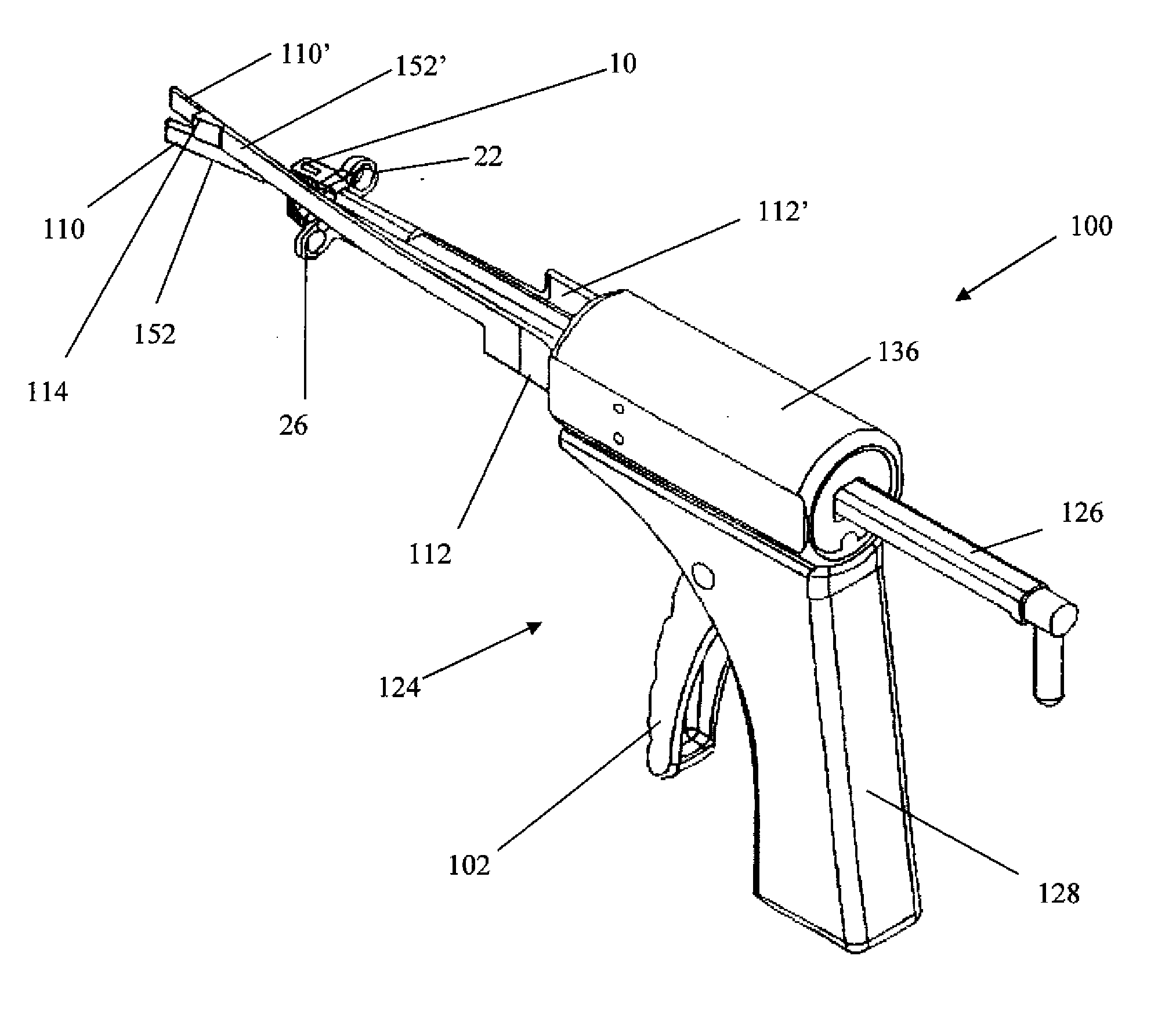
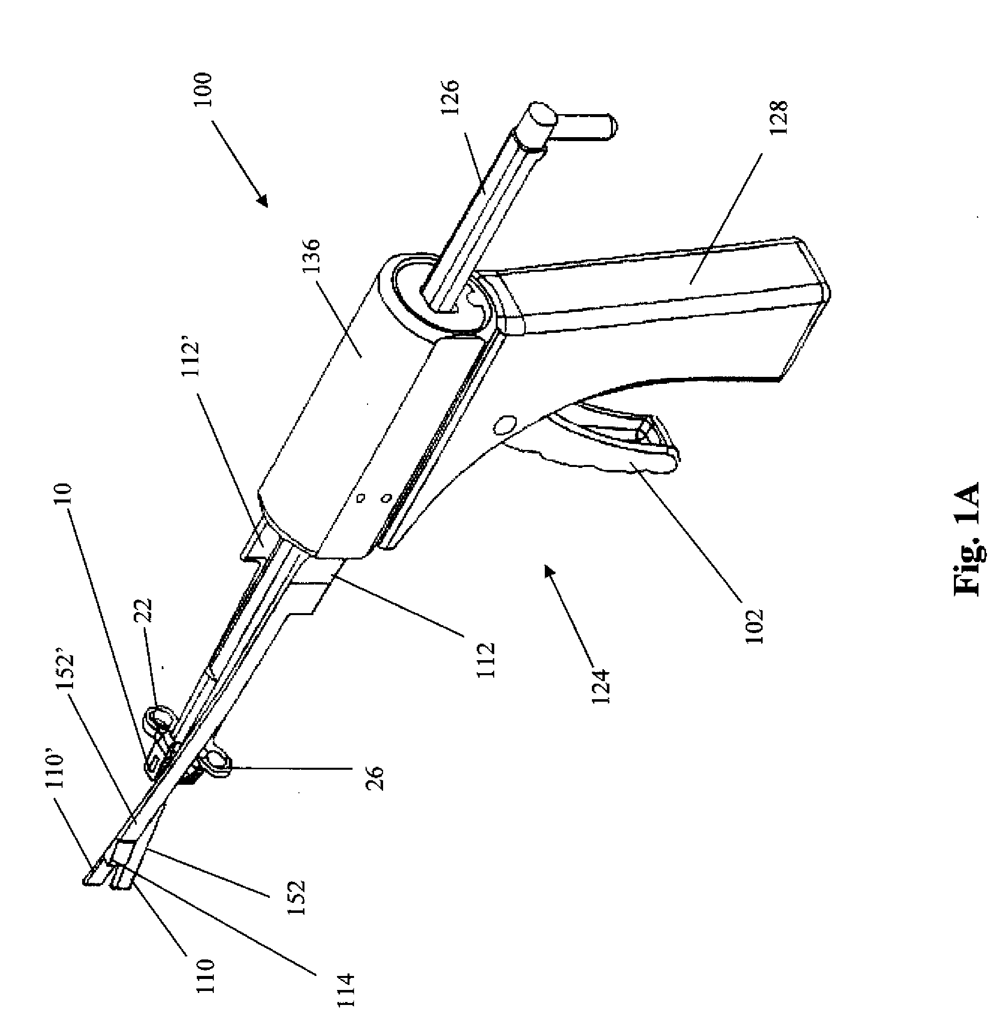
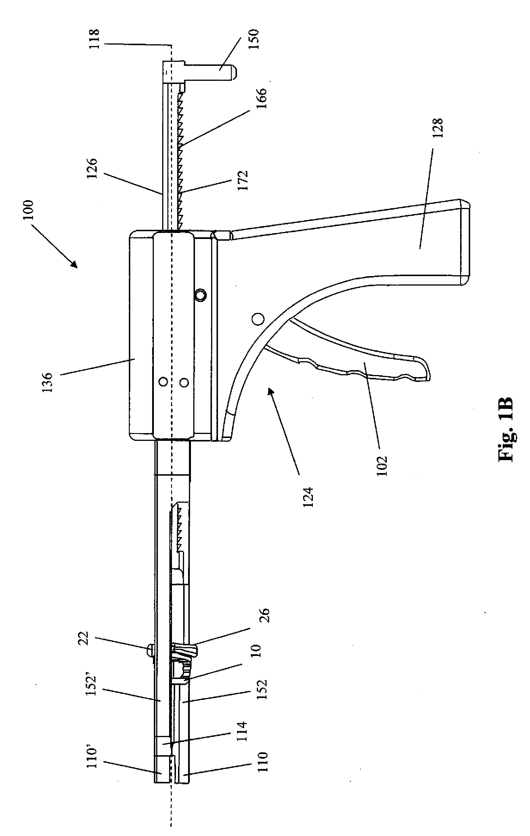
[0032]The invention disclosed herein provides an intervertebral implant and a tool to aid in intervertebral disc insertion for use in intervertebral disc replacement and / or spinal fusion. The tool is a device that allows a spinal surgeon to more easily access and position a replacement disc or graft within the vertebral space. The implant is adapted to ensure that the implant does not exceed a predefined implantation depth, and in some embodiments to provide a means for attaching the implant to e.g. the vertebral body. In particular, the implant comprises a proximal end having at least one flange, which limits the distal progress of the implant as it is being advanced into the intervertebral space. The implant is designed so that when the implant has advanced to a predetermined depth into the intervertebral space, at least one flange makes contact with at least one vertebral body, thereby stopping advancement of the implant into the intervertebral space. Thus, the implant allows a s...


PUM


Abstract

Provided herein is a vertebral distractor-inserter comprising a pair of arms comprising a first arm having a proximal end and a distal end and a second arm having a proximal end and a distal end, wherein the distal end of the first opposing arm is laterally offset from the distal end of a second arm thereby comprising a pair of laterally offset opposing arms, a driving rod extending between the pair of laterally offset opposing arms, and a drive mechanism in mechanical communication with the driving rod. A vertebral distractor-inserter comprising a pair of opposing arms, a housing in mechanical communication with the arms and rotatable about an axis extending between the arms, and a driving rod extending through at least a portion of the housing and between the arms. A vertebral distractor-inserter adapted for single-handed use. A vertebral distractor-inserter having an implant depth adjustor. Methods for distracting adjacent vertebrae and inserting an implant using the device described herein.

Description

BACKGROUND OF THE INVENTION[0001]Spinal disc replacement and / or spinal fusion are sometimes necessary for patients having lumbar degenerative disc disease. It has been estimated that at least 30% of people aged 30 to 50 will have some degree of disc space degeneration, although not all will have pain or ever be diagnosed formally with degenerative disc disease. After a patient reaches 60, it is more normal than not to have some level of disc degeneration. A twisting injury often starts degenerative disc disease, but it can also be initiated by everyday wear and tear on the spine.[0002]Lower back pain is the most common symptom of a compromised disc emblematic of degenerative disc disease. For most patients with lumbar degenerative disc disease, the pain is for the most part tolerable and low-grade, but continuous with occasional flaring of intense pain. Pain can be simply centered on the lower back, or it can radiate to the hips and legs. It can get worse by sitting, or it can be in...

Claims


Application Information

Patent Timeline
Patent Type & Authority Applications(United States)
IPC IPC(8): A61B17/58
CPCA61B17/7059A61B2017/0256A61F2/4455A61F2/4611A61F2002/30578A61F2002/4628A61F2002/30774A61F2002/30784A61F2002/30794A61F2002/30904A61F2002/4627A61F2002/30596A61F2002/30594A61F2002/3079
Inventor BLAIN, JASONJOHNSON, DEAN
Owner SPINAL ELEMENTS INC
Why Eureka
Try Eureka