Vehicle damping force control apparatus

a technology of damping force and control apparatus, which is applied in the direction of cycle equipment, transportation and packaging, instruments, etc., can solve the problems of vehicle turning, achieve the effect of suppressing the pitching of the vehicle body, suppressing the rise at the center of gravity, and enhancing the roll feeling

Inactive Publication Date: 2009-09-17
TOYOTA JIDOSHA KK
View PDF8 Cites 39 Cited by
  • Summary
  • Abstract
  • Description
  • Claims
  • Application Information

AI Technical Summary

Benefits of technology

[0006]The present invention is accomplished in view of the aforesaid problems, and aims to provide a damping force control apparatus that can suppress a pitching during the turning of a vehicle with a control of the damping force of front-wheel-side shock absorbers and the damping force of rear-wheel-side shock absorbers, considering jack-up force exerted on the vehicle body during the turning of the vehicle.

Problems solved by technology

However, in the damping force control apparatus disclosed in the Japanese Patent No. 3509544, the damping forces of the front-wheel-side shock absorbers corresponding to the front wheels and the damping forces of the rear-wheel-side shock absorbers corresponding to the rear wheels are independently controlled, in which the balance of the input applied to the front-wheel-side vehicle body and the rear-wheel-side vehicle body in the vertical direction is not at all considered.
Therefore, a difference is caused between the jack-up forces exerted on the front-wheel-side vehicle body and the rear-wheel-side vehicle body, or between the inputs applied to the front-wheel-side vehicle body and the rear-wheel-side vehicle body in the vertical direction due to the vehicle structure and weight balance, so that a problem of occurring a pitching during the turning of the vehicle arises.

Method used


Image

  • Vehicle damping force control apparatus
  • Vehicle damping force control apparatus
  • Vehicle damping force control apparatus

Examples


first embodiment

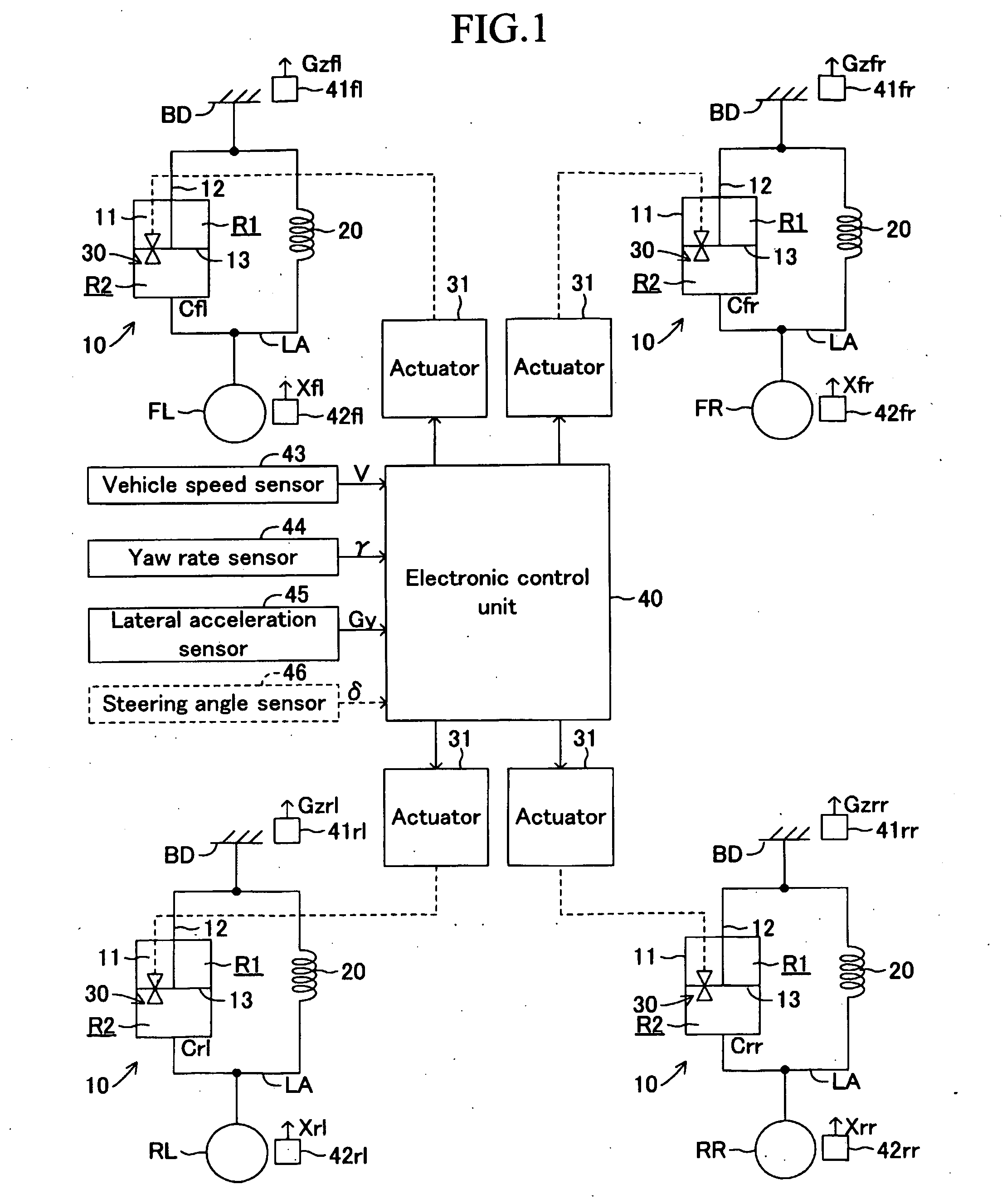
[0035]A first embodiment according to the present invention will be explained hereinafter with reference to the drawings. FIG. 1 is a schematic diagram showing an overall of a vehicle damping force control apparatus according to the first embodiment. This damping force control apparatus has shock absorbers 10 and springs 20 between a vehicle body BD (sprung member) and the respective front left wheel FL, front right wheel FR, rear left wheel RL and rear right wheel RR.

[0036]Each of the shock absorbers 10 is disposed between an unsprung member LA that functions as a suspension system composed of a lower arm and knuckle connected to each of the front left wheel FL, front right wheel FR, rear left wheel RL and rear right wheel RR and the vehicle body BD (sprung member). It is coupled to the unsprung member LA at the lower end of a cylinder 11 and fixed to the vehicle body BD at the upper end of a piston rod 12 that is inserted into the cylinder 11 so as to be capable of moving up and d...

modified example

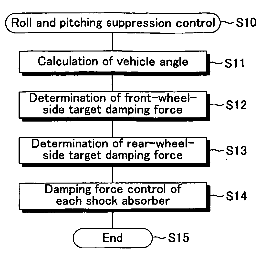
[0088]Subsequently, a modified example of the first embodiment will be explained. In this modified example, the electronic control unit 40 executes the roll and pitching suppression control program shown in FIG. 3, and executes the front-wheel-side target damping force determination program (see FIG. 6) at step S12, like the first embodiment. It should be noted that, in this modified example, instead of referring to the target pitch angle table shown in FIG. 9, the target pitch angle table shown in FIG. 11 is referred to in the execution of the process at step S41 in the front-wheel-side target damping force determination program. The other sections are same as those in the first embodiment.

[0089]In this modified example, the total Tr of the damping forces generated by the rear-wheel-side shock absorbers 10 is set at the rear-wheel-side vehicle body by the processes at steps S57 and S58 shown in FIG. 7 so as to overcome the rear-wheel-side jack-up force Jr, like the first embodiment...

second embodiment

[0092]Subsequently, a second embodiment of the present invention will be explained. The damping force control apparatus according to the second embodiment has a steering angle sensor 46 as shown by a broken line in FIG. 1. The steering angle sensor 46 detects a steering angle δ of a steering handle not shown. The steering angle δ represents the steering angle of a steering handle upon the turning in the leftward direction or rightward direction by the positive or negative value. The electronic control unit 40 according to the second embodiment executes a front-wheel-side and rear-wheel-side target damping force determination program shown in FIG. 12, instead of the front-wheel-side target damping force determination program at step S12 (see FIG. 6) and the rear-wheel-side target damping force determination program at step S13 (see FIG. 7), during the execution of the roll and pitching suppression control program shown in FIG. 3. The other sections are same as those in the first embo...


PUM


Abstract

A damping force control apparatus has shock absorbers 10 each being capable of changing damping force. An electronic control unit 40 calculates estimated roll angle and estimated pitch angle of a vehicle body BD in accordance with sprung accelerations detected by sprung acceleration sensors 41 fl to 41rr, calculates a target pitch angle from the estimated roll angle, and determines target damping force required for front-wheel-side shock absorbers 10 such that the estimated pitch angle coincides with the target pitch angle. The electronic control unit40 calculates rear-wheel-side jack-up force exerted on the rear-wheel-side vehicle body in accordance with vehicle speed detected by a vehicle speed sensor 43, yaw rate detected by a yaw rate sensor 44 and lateral acceleration detected by a lateral acceleration sensor 45, and determines the force in the direction for overcoming the calculated jack-up force as target damping force of rear-wheel-side shock absorbers 10. The electronic control unit 40 controls the operation of each actuator 31 in accordance with the rear-wheel-side and front-wheel-side target damping forces.

Description

TECHNICAL FIELD[0001]The present invention relates to a vehicle damping force control apparatus provided with shock absorbers capable of changing damping force, and more particularly, to a vehicle damping force control apparatus that controls damping force of each shock absorber during the turning of the vehicle for enhancing driveability of the vehicle.BACKGROUND ART[0002]Conventionally, there has been widely known, as this type of a damping force control apparatus, the one in which a virtual vehicle model having mounted at a virtual point at the inner side of the turning locus a lift-suppression-use shock absorber for suppressing a lift-up of a vehicle body and a roll-suppression-use shock absorber for suppressing a roll of the vehicle body is adapted to an actual vehicle model having shock absorbers disposed between the vehicle body and each of four wheels, as disclosed in the Japanese Patent No. 3509544.[0003]In this damping force control apparatus, a difference is produced betw...

Claims


Application Information

Patent Timeline
Patent Type & Authority Applications(United States)
IPC IPC(8): B60G17/016
CPCB60G17/0162B60G2800/912B60G2400/0512B60G2400/0523B60G2400/0532B60G2400/102B60G2400/104B60G2400/204B60G2400/252B60G2400/41B60G2500/10B60G2600/12B60G2600/124B60G2600/184B60G2800/0122B60G2800/014B60G2800/016B60G2800/24B60G17/08
Inventor TOMIDA, KOICHIMIZUGUCHI, YUSUKE
Owner TOYOTA JIDOSHA KK
Why Eureka
Try Eureka