

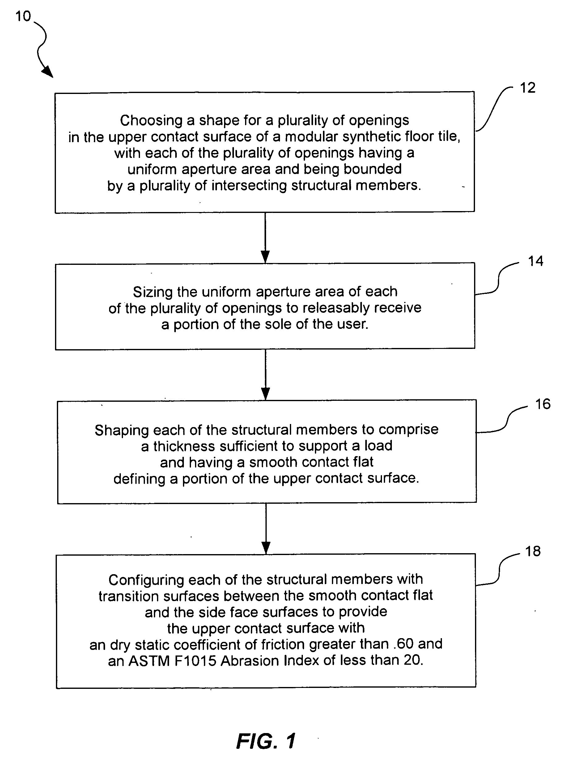
Method of Making A Modular Synthetic Floor Tile Configured For Enhanced Performance
a technology of synthetic floor tiles and modules, applied in the field of synthetic floor tiles, can solve the problems of reducing traction, increasing the abrasion of the contact surface, and increasing the likelihood of injury, so as to increase the traction about the contact surface, increase the traction, and increase the traction
- Summary
- Abstract
- Description
- Claims
- Application Information
AI Technical Summary
Benefits of technology
Problems solved by technology
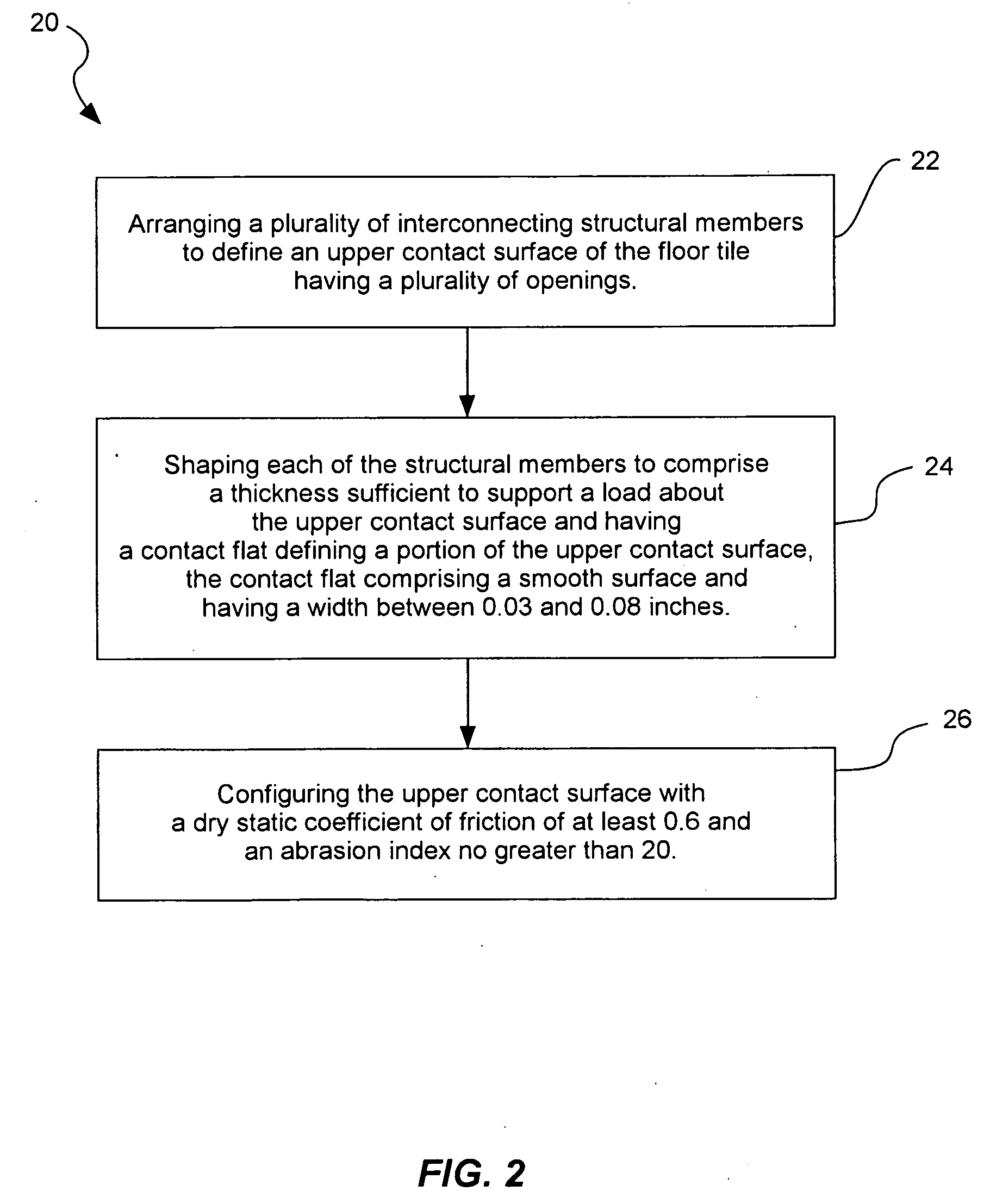
Method used
Image

Examples
Embodiment Construction
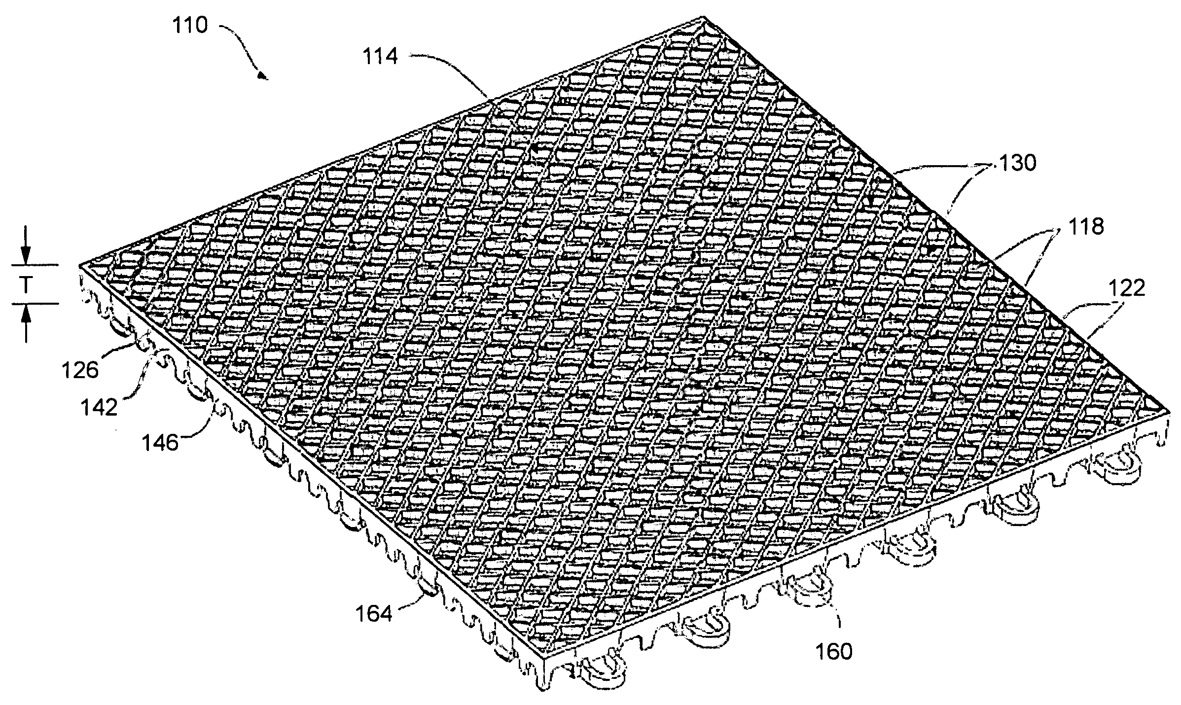
[0033]The following detailed description of exemplary embodiments of the invention makes reference to the accompanying drawings, which form a part hereof and in which are shown, by way of illustration, exemplary embodiments in which the invention may be practiced. While these exemplary embodiments are described in sufficient detail to enable those skilled in the art to practice the invention, it should be understood that other embodiments may be realized and that various changes to the invention may be made without departing from the spirit and scope of the present invention. Thus, the following more detailed description of the embodiments of the present invention is not intended to limit the scope of the invention, as claimed, but is presented for purposes of illustration only and not limitation to describe the features and characteristics of the present invention, to set forth the best mode of operation of the invention, and to sufficiently enable one skilled in the art to practic...
PUM
| Property | Measurement | Unit |
|---|---|---|
| Length | aaaaa | aaaaa |
| Length | aaaaa | aaaaa |
| Thickness | aaaaa | aaaaa |
Abstract
Description
Claims
Application Information