Pedal apparatus of electronic musical instrument

Active Publication Date: 2009-09-24
YAMAHA CORP
View PDF1 Cites 19 Cited by
  • Summary
  • Abstract
  • Description
  • Claims
  • Application Information

AI Technical Summary

Benefits of technology

[0006]The present invention was accomplished to solve the above-described problem, and an object thereof is to provide a pedal apparatus of an electronic musical instrument, the pedal apparatus achieving light weight and allowing a player to feel as if the player were manipulating a damper pedal of an acoustic piano.
[0054]Then, if the amount of depression of the lever (140) increases further, so that the force exerted by the lever (140) through the second spring (167) to lift the second movable supporting member (163, 165) exceeds the weight of the second movable supporting member (163, 165), the second movable supporting member (163, 165) starts being displaced upward. The amount of depression of the lever (140) at the start of the upward displacement of the second movable supporting member (163, 165) corresponds to the first amount of depression. Then, if the amount of depression of the lever (140) increases further from this state, the second movable supporting member (163, 165) is displaced upward. In this state, the second spring (167) will not be compressed any further. In this state, therefore, although the spring force of the first spring (166) and the spring force of the second spring (167) are exerted on the lever (140) in parallel, the spring force of the second spring (167) will not change, with the spring force of only the first spring (166) increasing. As a result, the further specific invention can make the rate of change in the reaction force of the lever (140) increase and decrease stepwise according to the amount of depression of the lever (140) to start with a low rate of change to increase to a high rate to be followed by a low rate. Therefore, the further specific invention can provide the player with feeling similar to that the player perceives when he manipulates a damper pedal of an acoustic piano as shown by the solid line in FIG. 34. Similarly to the another specific invention described with reference to FIG. 27, in addition, the further specific invention can stabilize the reaction force of the lever (140). Furthermore, the further specific invention can realize the desired capabilities with the simple structure.

Problems solved by technology

In a range of A0 of FIG. 34 where the damper pedal is depressed shallowly, therefore, the manipulation of the pedal will not be conveyed to the dampers, resulting in a small rate of change in the reaction force of the pedal.
However, the conventional pedal apparatus of an electronic musical instrument as described above fails to provide the player with the feeling that the player of an acoustic piano perceives at the range of A2 of FIG. 34 (the state where the rate of change in the reaction force reduces again) which follows the range A1 of FIG. 34.

Method used


Image

  • Pedal apparatus of electronic musical instrument
  • Pedal apparatus of electronic musical instrument
  • Pedal apparatus of electronic musical instrument

Examples


first embodiment

b. First Embodiment

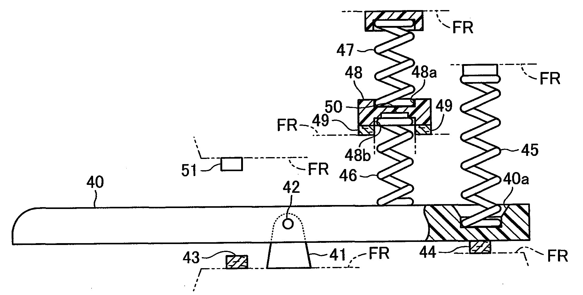
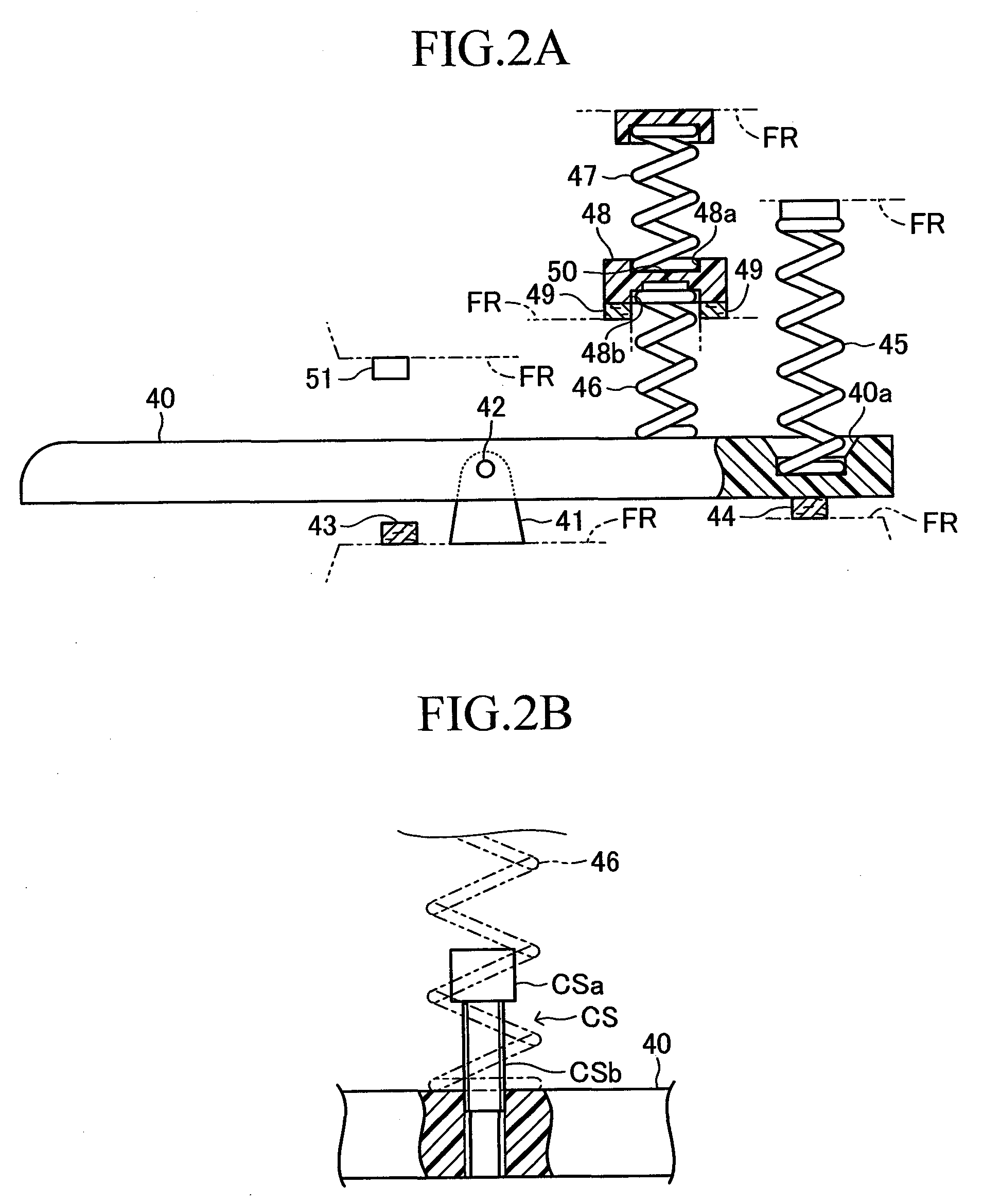
[0132]Next, a first embodiment of the pedal apparatus 12 according to the present invention will be described in detail. FIG. 2A shows a side view of the pedal apparatus of the electronic musical instrument according to the present embodiment. A lever 40 is a long plate-shaped member. The forward part (left side in FIG. 2A) of the lever 40 is a wide depression part on which a player steps. The lever 40 is supported at a middle part thereof by a lever supporting portion 41 provided on a frame FR which serves as a fixed supporting member so that the front end of the lever 40 can pivot upward and downward about a rotary shaft 42. Below the middle part of the lever 40, a long lower limit stopper 43 made of a shock-absorbing member such as felt extends in a lateral direction to be fixed to the frame FR. The lower limit stopper 43 restricts downward displacement of the forward part of the lever 40. The frame FR is a structural body for supporting various parts of the pe...

second embodiment

c. Second Embodiment

[0154]Next, a second embodiment of the pedal apparatus 12 according to the present invention will be described in detail. FIG. 8 is a side view of the pedal apparatus 12 according to the present embodiment. The lever 40, the lever supporting portion 41, the lower limit stopper 43 and the upper limit stopper 44 are similar to those of the first embodiment. Into a concave portion 40c provided on the top surface of the rear part of the lever 40 to be situated behind the rotary shaft 42 of the lever 40, the lower end of a drive rod 52 is inserted to be in contact with the bottom surface of the concave portion 40c. The drive rod 52, which is a long member, extends upward from the rear part of the lever 40. The top end of the drive rod 52 is inserted into a concave portion 53a provided on the undersurface of a first movable supporting member 53 to be in contact with the upper bottom surface of the concave portion 53a. By a guide member which is not shown, the drive rod...

third embodiment

d. Third Embodiment

[0170]Next, a third embodiment of the pedal apparatus 12 according to the present invention will be described in detail. FIG. 10 is a side view of the pedal apparatus 12 according to the present embodiment. The lever 40 and the lower limit stopper 43 are similar to those of the first embodiment. The rear end of the lever 40 is supported by a lever supporting portion 80 provided on the frame FR so that the front end of the lever 40 can pivot upward and downward about a rotary shaft 81. Below the middle part of the lever 40, the lower end of a first spring 82 is fixed to the frame FR, with the top end of the first spring 82 being inserted into a concave portion 40e provided on the undersurface of the lever 40 to be in contact with the upper bottom surface of the concave portion 40e to urge the forward part of the lever 40 upward. The first spring 82 is a compression spring.

[0171]Above the middle part of the lever 40, the top end of a second spring 83 is fixed to the...


PUM


Abstract

A lever 40 is supported by a lever supporting portion 41. The lever 40 is urged by a first spring 45 and a second spring 46. The urging force of the first spring 45 varies over the entire operational range of the lever 40. The second spring 46 and a third spring 47 are provided serially through a movable supporting member 48. The displacement of the movable supporting member 48 is restricted by a fixed supporting member FR. If the urging force of the second spring 46 exceeds the urging force of the third spring 47, the restriction on the displacement of the movable supporting member 48 is removed. Therefore, the present invention provides a player with feeling similar to that the player perceives when he manipulates a damper pedal of an acoustic piano.

Description

BACKGROUND OF THE INVENTION[0001]1. Field of the Invention[0002]The present invention relates to a pedal apparatus of an electronic musical instrument, the pedal apparatus controlling the manner in which a musical tone is generated.[0003]2. Description of the Related Art[0004]Conventionally, it is known that a pedal apparatus of an electronic musical instrument is designed to provide a player with a feeling similar to that perceived by a player on manipulation of a pedal of an acoustic piano. For example, Japanese Unexamined Patent Publication No. 2004-334008 discloses a pedal apparatus which has a lever that pivots in response to a depression of a pedal and a first spring and a second spring provided in parallel in order to urge the lever. The disclosed pedal apparatus is designed such that only the first spring urges the lever if the lever is shallowly depressed, whereas the first spring and the second spring urge the lever if the lever is depressed by a certain amount or more. Th...

Claims


Application Information

Patent Timeline
IPC IPC(8): G10C3/26
CPCG10H1/348G10H1/346
Inventor IWAMOTO, TOSHIYUKIKITAJIMA, MITSURUMURAMATSU, SHIGERUSAIGO, KOICHI
Owner YAMAHA CORP
Why Eureka
Try Eureka