
Reducing cross modulation in multichannel modulated optical systems with Anti-clipping

a multi-channel modulated optical system and anti-clipping technology, applied in the field of modulated optical systems, can solve problems such as clipping, bit errors in the optical output of lasers, and added to analog channels even more sensitive to noise arising

Active Publication Date: 2009-09-24
APPLIED OPTOELECTRONICS
View PDF36 Cites 11 Cited by
  • Summary
  • Abstract
  • Description
  • Claims
  • Application Information

AI Technical Summary

Problems solved by technology

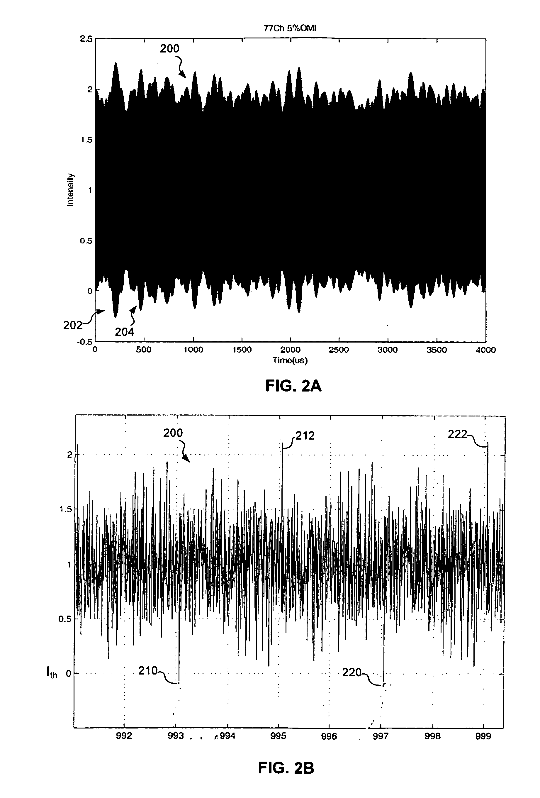
Although the laser output may be generally linear along a significant portion of the L-I curve, the light output may attain a zero-power level when the input current falls below a threshold current level, which results in an effect known as clipping.
As a result of this occasionally occurring peak voltage (and thus peak drive current) condition, the laser may be driven into hard limiting, causing clipping, when a sufficient number of carriers are in phase alignment.
When such clipping occurs, intermodulation products (i.e., clipping-induced distortion) and noise may be generated, which may result in bit errors in the optical output of the laser.
Systems including a digital signal (e.g., a QAM signal) added to the analog channels are even more sensitive to noise arising from clipping.
Driving the individual channels too much, however, may cause clipping when the channels line up, as described above.
This approach may result in large swings of bias current, however, during periods of significantly lower power in the RF signal.
This may have undesirable effects, such as causing or contributing to cross modulation.

Method used


Image

  • Reducing cross modulation in multichannel modulated optical systems with Anti-clipping
  • Reducing cross modulation in multichannel modulated optical systems with Anti-clipping
  • Reducing cross modulation in multichannel modulated optical systems with Anti-clipping

Examples


Embodiment Construction

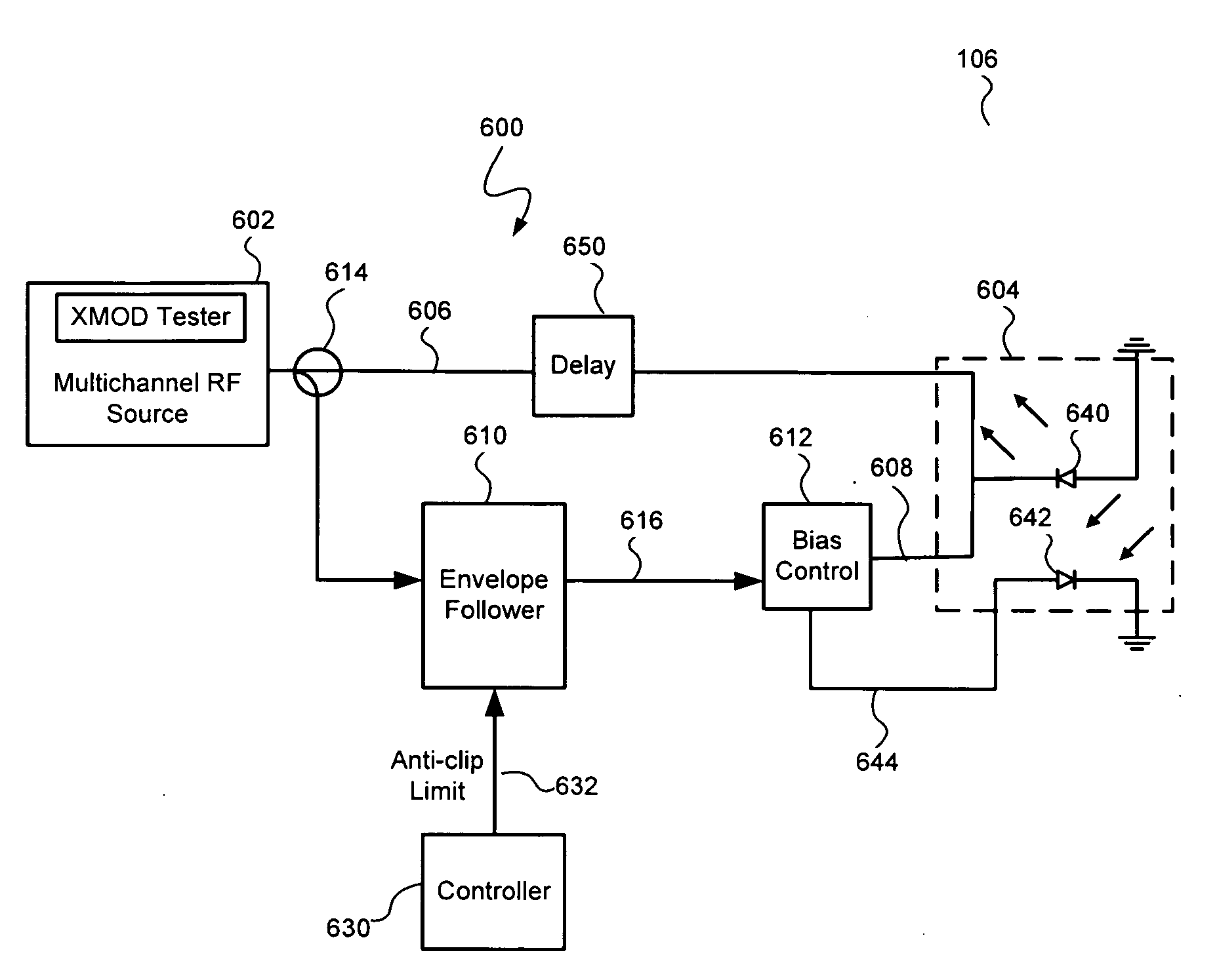
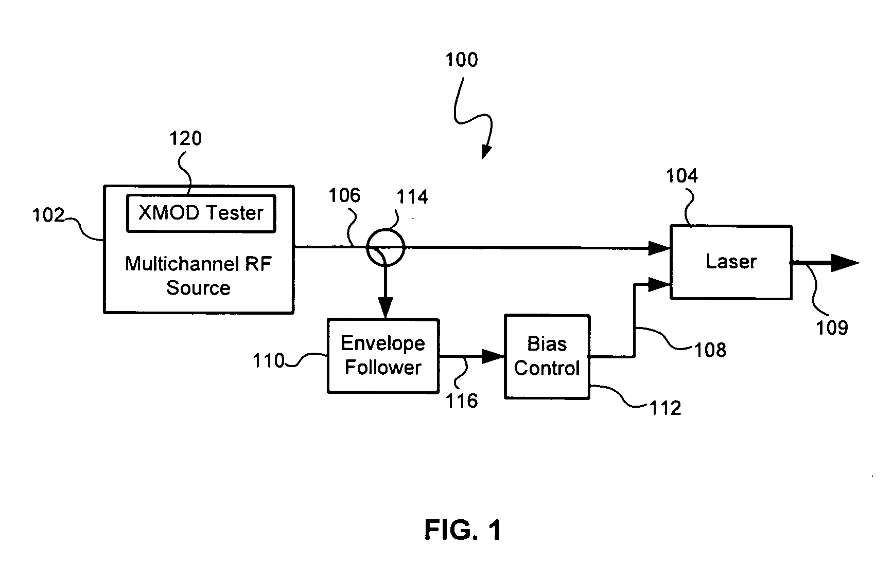
[0021]Referring to FIG. 1, a modulated optical system 100 with anti-clipping, consistent with embodiments of the present invention, is capable of providing both reduced clipping and reduced cross modulation. The modulated optical system 100 generally includes a laser 104 that receives a multichannel RF signal 106 from a multichannel RF source 102. The laser 104 may include a RF input that receives the multichannel RF signal 106, a bias current input that receives a bias current 108, and an optical output that produces a modulated optical signal 109 in response to the RF signal 106 and the bias current 108. The system 100 may also include other circuitry and / or components (not shown) between the multichannel RF source 102 and the laser 104 such as, for example, one or more predistortion circuits and a laser driver circuit.

[0022]By adjusting the bias current 108 in response to an envelope of the multichannel RF signal 106, the system 100 reduces or corrects clipping that might occur i...


PUM


Abstract

A modulated optical system with anti-clipping reduces or corrects clipping that might occur in the laser as a result of negative spikes or peaks in a multichannel RF signal. The system generally detects an envelope of the RF signal to generate an anti-clipping signal that follows at least a portion of the envelope and prevents one or more negative peaks from causing clipping by adjusting a bias current in response to the anti-clipping signal. The system may also reduce cross modulation by clamping the anti-clipping signal at an anti-clipping limit during lower power periods of the RF signal.

Description

TECHNICAL FIELD[0001]The present invention relates to modulated optical systems and more particularly, to a system and method for reducing cross modulation in multichannel modulated optical systems with anti-clipping.BACKGROUND INFORMATION[0002]A directly modulated laser may be used as an optical transmitter that transmits light at a given wavelength. The power (i.e., amplitude) of the laser light is modulated by corresponding modulation of the current used to drive the laser. For example, the optical transmitter may be modulated to carry a wide-band RF signal. In this case, the electrical current that drives or pumps the laser is modulated with the wide-band RF signal. The relationship between the light output and the input current for such a laser may be represented using a transfer curve or L-I (light-current) curve. The set point of the L-I curve may be selected so as to maximize the linearity of the laser output in response to the modulation, within the expected range of operat...

Claims


Application Information

Patent Timeline
Patent Type & Authority Applications(United States)
IPC IPC(8): H03C1/06
CPCH04B10/25751H04B10/58
Inventor ZHENG, JUNISHAUG, BRIAN
Owner APPLIED OPTOELECTRONICS
Learn More