System and methods for the improvement of images generated by fiberoptic imaging bundles

a fiberoptic imaging and bundle technology, applied in the field of medical devices, can solve the problems of inability to configure video or electronic endoscopes at small sizes to be used in areas of the body requiring a thin or ultra thin endoscop

Inactive Publication Date: 2009-09-24
BOSTON SCI SCIMED INC
View PDF15 Cites 40 Cited by
  • Summary
  • Abstract
  • Description
  • Claims
  • Application Information

AI Technical Summary

Problems solved by technology

Video or electronic endoscopes, however, are typically incapable of being configured at small sizes to be used in areas of a body requiring a thin or ultra thin endoscope.

Method used


Image

  • System and methods for the improvement of images generated by fiberoptic imaging bundles
  • System and methods for the improvement of images generated by fiberoptic imaging bundles
  • System and methods for the improvement of images generated by fiberoptic imaging bundles

Examples


Embodiment Construction

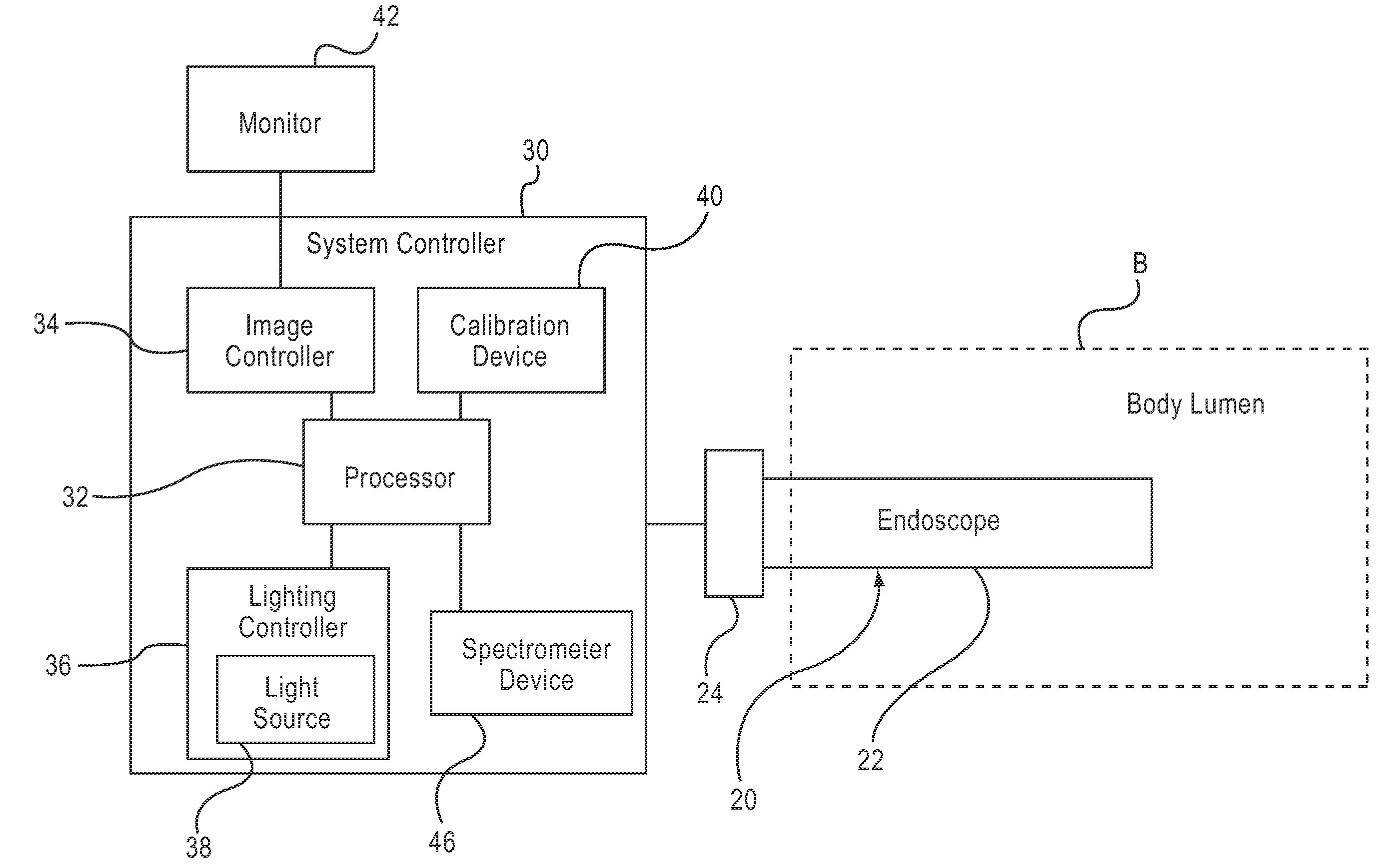
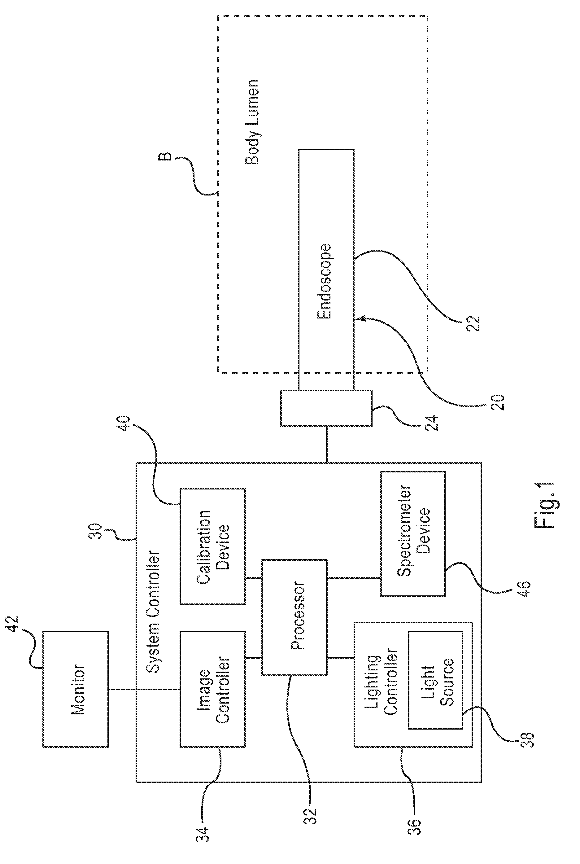
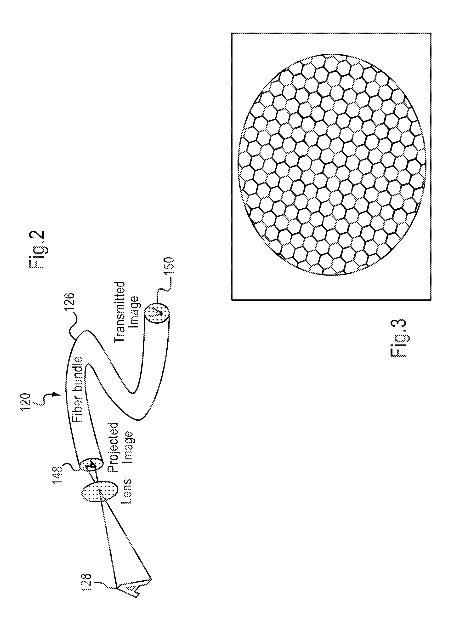
[0016]The devices and methods described herein are generally directed to the use of an endoscope, and more specifically a fiberoptic endoscope, within a body lumen of a patient. For example, the devices and methods are suitable for use within a gastrointestinal lumen or a ureter. An endoscope system as described herein can be used to illuminate a body lumen and provide an image of the body lumen or an object within the body lumen, that has improved quality over images produced by known fiberoptic endoscopes and systems. For example, devices and methods are described herein that can reduce or remove the “honeycomb” pattern from an image before it is displayed, for example, on a video monitor. Such a “honeycomb” effect as referred to herein can result from the projection within the image of the space between fibers within a fiberoptic bundle of an endoscope.

[0017]In one embodiment, a method includes receiving a first optical image from an endoscope having a plurality of imaging fibers...


PUM


Abstract

A method according to an embodiment of the invention includes receiving a first optical image from an endoscope having a plurality of imaging fibers. A spatial frequency is identified that is associated with the plurality of imaging fibers. A second optical image is received from the endoscope. The spatial frequency is filtered from the second optical image. A method according to another embodiment includes producing an optical image of at least a portion of a body lumen using a fiberscope. The optical image is transmitted to a video camera coupled to the fiberscope. A honeycomb pattern associated with a fiber bundle of the fiberscope is removed from the optical image. In some embodiments, the honeycomb pattern can be removed in substantially real time. In some embodiments, prior to producing the optical image, a calibration cap is coupled to the fiberscope and used in a calibration process.

Description

CROSS-REFERENCE TO RELATED APPLICATIONS[0001]This application claims priority to U.S. Provisional Patent Application Ser. No. 61 / 038,233, entitled “System and Methods for the Improvement of Images Generated by Fiberoptic Imaging Bundles,” filed Mar. 20, 2008, the disclosure of which is incorporated herein by reference in its entirety.BACKGROUND[0002]The invention relates generally to medical devices and more particularly to endoscopic imaging devices and methods for using such devices.[0003]A variety of known types of endoscopes can be used for various medical procedures, such as procedures within a urogenital or gastrointestinal system and vascular lumens. Some known endoscopes include optical fibers for providing imaging capabilities via a remote sensor. Such endoscopes are often referred to as fiberscopes to differentiate them from video or electronic endoscopes that include a semiconductor imager within the endoscope, and the image is transmitted electronically from the endoscop...

Claims


Application Information

Patent Timeline
Patent Type & Authority Applications(United States)
IPC IPC(8): H04N7/18
CPCA61B1/00165A61B1/045G02B27/46G06T5/10G06T2207/10068G06T2207/20056A61B1/00009H04N9/735H04N17/002H04N2005/2255G06T5/002G06T5/20G06T2207/30028A61B1/000095H04N23/555H04N23/88
Inventor MODELL, MARK D.ROBERTSON, DAVID W.SPROUL, JASON Y.
Owner BOSTON SCI SCIMED INC
Why Eureka
Try Eureka