Lens driving apparatus

a driving apparatus and lens technology, applied in the direction of printers, cameras, instruments, etc., can solve the problems of easy breakage of electronic appliances, and achieve the effects of saving manufacturing costs, reducing parts, and simplifying assembly procedures

Active Publication Date: 2009-09-24
LG INNOTEK CO LTD
View PDF2 Cites 34 Cited by
  • Summary
  • Abstract
  • Description
  • Claims
  • Application Information

AI Technical Summary

Benefits of technology

[0008]According to the lens driving apparatus of the embodiment, a yoke is directly coupled to a base and parts are installed in a space formed in an inner portion of the base and the yoke. Accordingly, since an additional case is not necessary, the number of parts is reduced, an assembly procedure is simplified, and thus the manufacturing cost can be saved.
[0009]Further, according to the lens driving apparatus of the embodiment, the base is coupled to the yoke while maintaining a sealing status by locking holes of the base and locking protrusions of the yoke. That is, any gap does not exist in the sides of the base and the yoke, a hole of the yoke is shielded by a lens module, and a through hole of the base is closely coupled to an electronic appliance, so that impurities can be prevented from penetrating into the inner space formed be the base and the yoke. As a result, the parts are not damaged by the impurities.
[0010]Furthermore, when a prism magnet is used, since the manufacturing cost is saved as compared with a case of using a ring-shaped magnet, the economical efficiency can be improved.

Problems solved by technology

Further, since electronic appliances having cameras therein may be easily exposed to external environment or impact in terms of the characteristics of portable electronic appliances, external impurities may easily penetrate into the electronic appliances or the electronic appliances may be easily broken by the impact.

Method used


Image

  • Lens driving apparatus
  • Lens driving apparatus
  • Lens driving apparatus

Examples


Embodiment Construction

[0015]Hereinafter, a lens driving apparatus according to an embodiment will be described with reference to accompanying drawings.

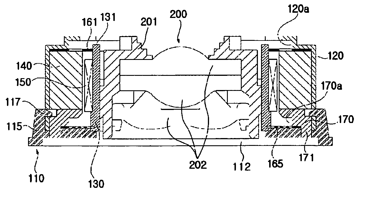
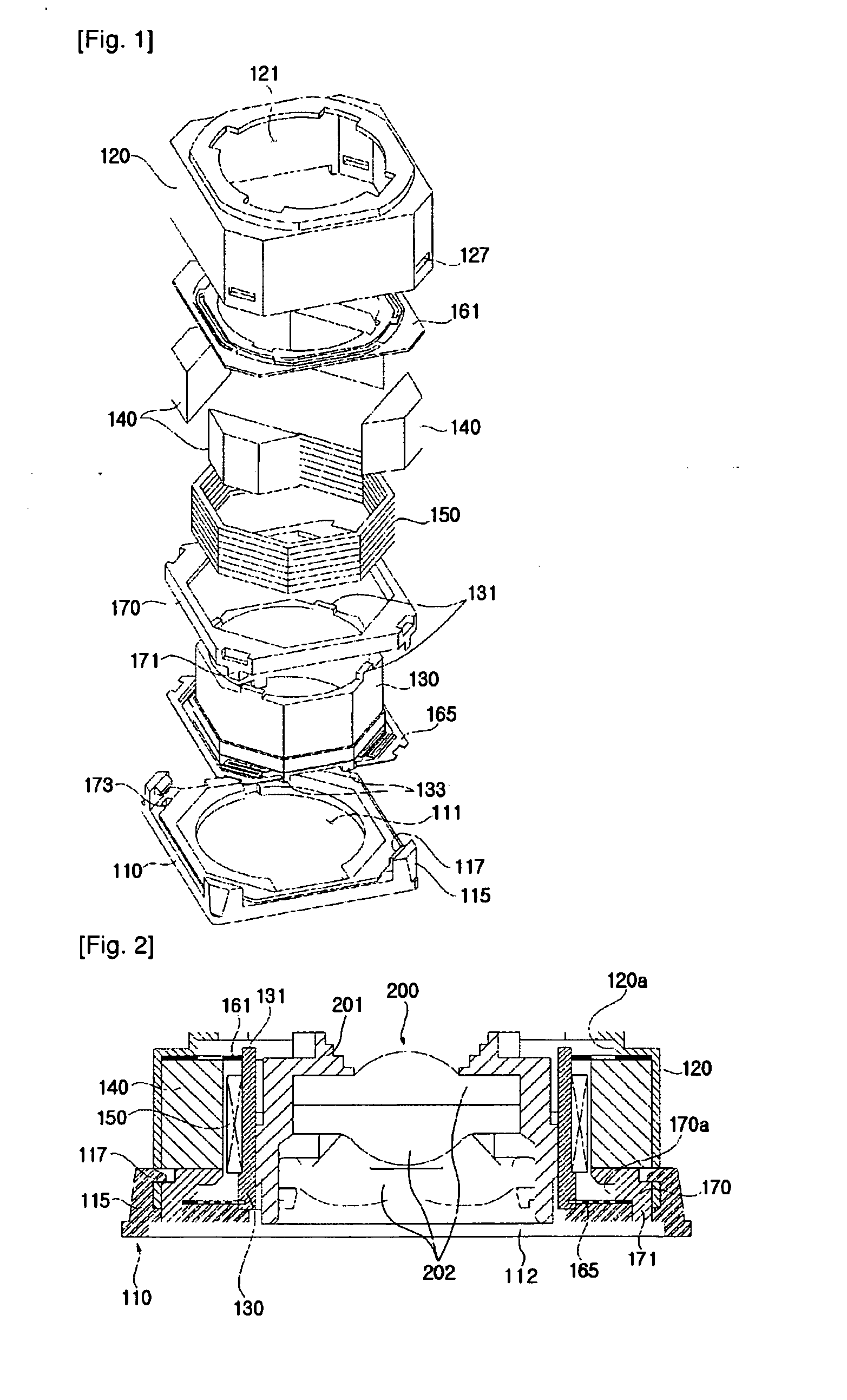
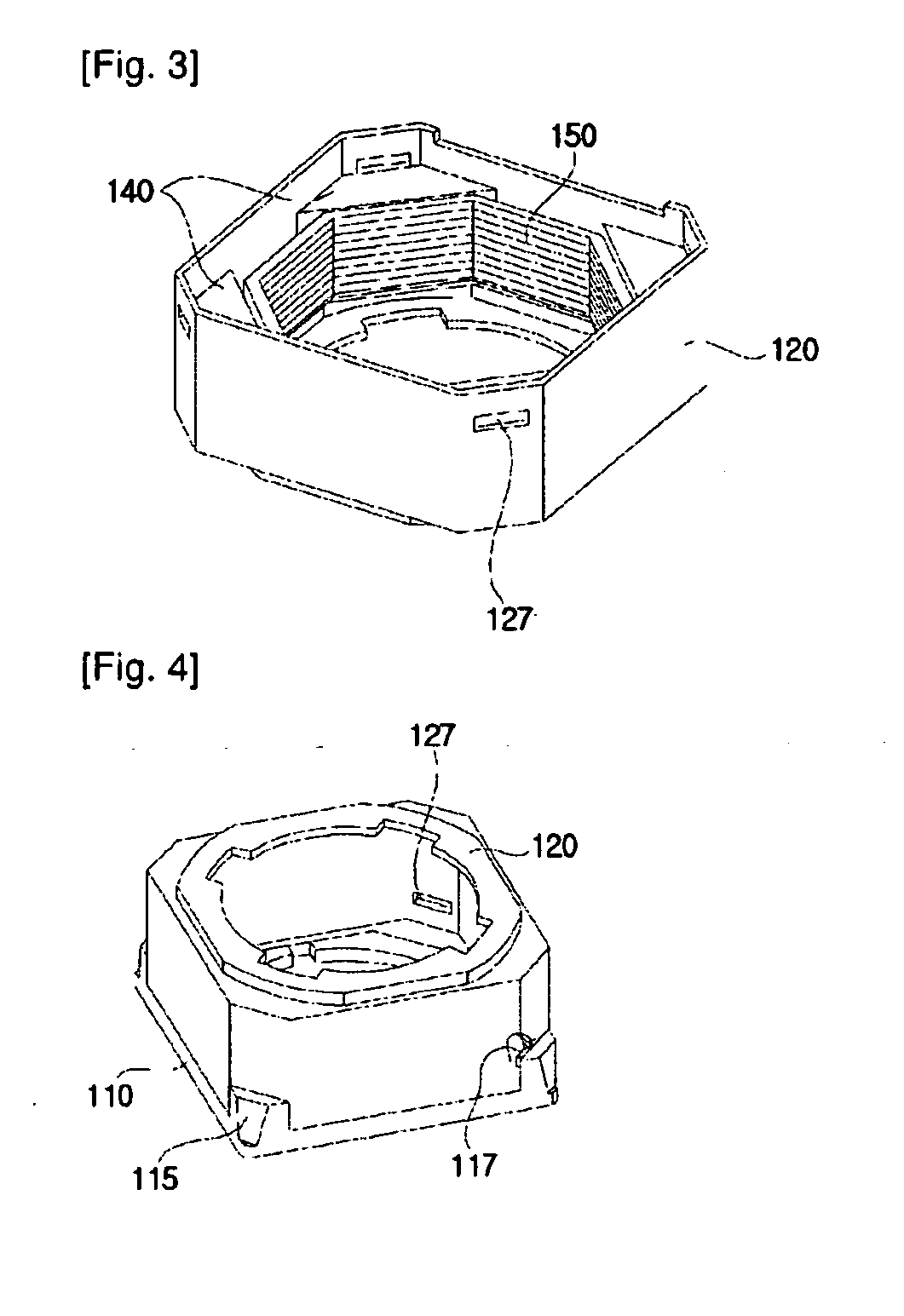
[0016]FIG. 1 is an exploded perspective view showing the lens driving apparatus according to the embodiment, FIG. 2 is a sectional view showing the lens driving apparatus in FIG. 1, and FIG. 3 is a perspective view showing a state in which a magnet and a coil are installed at the yoke in FIG. 1.

[0017]As shown in FIGS. 1 and 2, the lens driving apparatus according to the embodiment comprises a base 110 and a metal yoke 120 which are coupled to each other to form a predetermined space.

[0018]The base 110 has a disc shape or a polygonal plate shape and is formed at the central portion thereof with a through hole 111. The bottom surface of the base 110 is coupled to an electronic appliance (not shown) and a circuit substrate 112 provided with an image sensor (not shown) is arranged in the through hole 111.

[0019]The yoke 120 is coupled to the base 110 to serve a...


PUM


Abstract

Disclosed is a lens driving apparatus. The lens driving apparatus comprises a base, a yoke coupled to the base, having an upper surface formed with a hole, a closed side surface, and an opened bottom surface, a bobbin movably installed in an inner portion of the yoke, a lens module coupled to the bobbin to go in and out the hole according to movement of the bobbin, a magnet fixed to an inner portion of the yoke, a coil fixed to an outer portion of the bobbin while facing the magnets, and springs coupled to the bobbin to provide restoration force to the bobbin.

Description

TECHNICAL FIELD[0001]The present invention relates to a lens driving apparatus.BACKGROUND ART[0002]Recently, as electronic appliances have multi-functions, various electronic appliances having cameras therein, such as MP3 players, mobile communication terminals and PDAs, have been widely used.[0003]As electronic appliances having cameras therein are manufactured in a small size, parts for providing camera functions must also be manufactured in a small size.[0004]Further, since electronic appliances having cameras therein may be easily exposed to external environment or impact in terms of the characteristics of portable electronic appliances, external impurities may easily penetrate into the electronic appliances or the electronic appliances may be easily broken by the impact.DISCLOSURE OF INVENTIONTechnical Problem[0005]The embodiment provides a lens driving apparatus which can be designed in a simple structure and manufactured in a small size.[0006]The embodiment provides a lens dr...

Claims


Application Information

Patent Timeline
Patent Type & Authority Applications(United States)
IPC IPC(8): G02B7/02
CPCG02B7/023G03B3/10G02B27/0006G11B7/0935H02K41/0356G11B7/0933G02B7/08H02K33/18
Inventor KIM
Owner LG INNOTEK CO LTD
Why Eureka
Try Eureka