
Apparatus and method of compensating for compact digital domain chromatic dispersion

a technology of chromatic dispersion and apparatus, applied in the field of optical communication, can solve the problems of physical large size, loss of information in the phase of optical signal, and not yet in widespread use, so as to reduce the amount of computation, reduce the number of computations, and save computation resources

Inactive Publication Date: 2009-09-24
HUAWEI TECH CO LTD
View PDF2 Cites 81 Cited by
  • Summary
  • Abstract
  • Description
  • Claims
  • Application Information

AI Technical Summary

Benefits of technology

[0017]The present invention reduces the number of computations needed to implement an FIR filter by approximating the actual filter coefficients to a limited set of allowed digitization values lying on a circle on the complex plane. Following this approximation, the same filter coefficients recur many times. A multiplication of a signal value by a certain filter coefficient may be executed in full once, and then reused many times without repeating the multiplication, so as to save on computation resources.
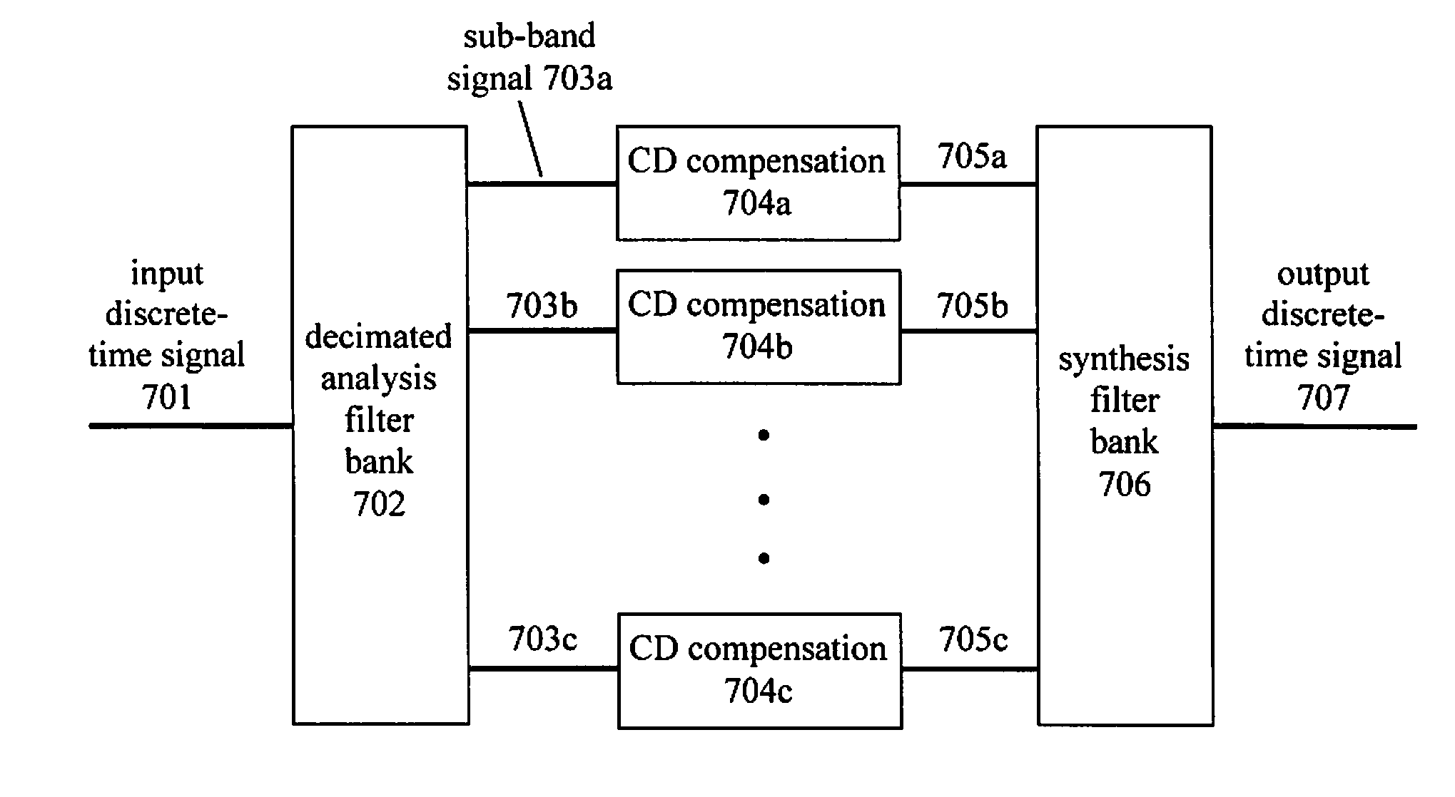
[0018]In one aspect, the present invention reduces the amount of computations by dividing the signal into several spectral sub-bands. The sub-bands are separately CD compensated, and then combined into a single output signal. The total amount of computations to compensate for CD on all the sub-bands plus performing the sub-band filtering is less than the amount of computations to compensate for CD directly.

Problems solved by technology

There are several advantages to imposing information by modulating the electric field, but it is not yet in widespread use because the receiver is more complex.
Thus, any information in the phase of the optical signal is lost.
DCF has the positive feature that it compensates exactly for chromatic dispersion, but it has disadvantages that it is expensive, it is physically large in size, it has substantial optical loss, and the amount of CD being compensated is fixed.
However electrical compensation of CD following direct detection can only compensate for a small amount of chromatic dispersion, equivalent to perhaps 100 km of NDSF at 10 Gb / s, because direct detection discards the phase of the optical signal.
When a small number of binary digits is used to represent a variable, it makes the CD compensation less accurate, but it saves on integrated circuit resources.
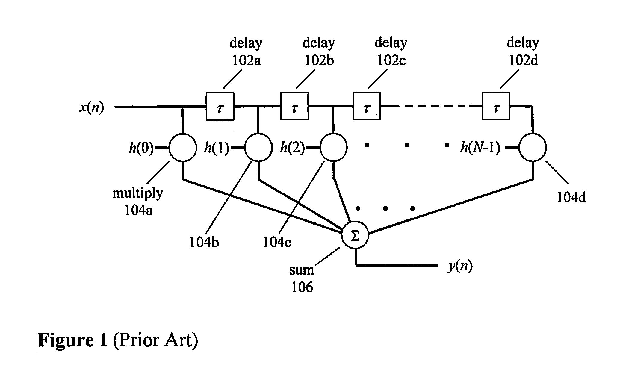
However, the digital signal processor in an actual implementation is likely to be organized in a parallel architecture, and there is a difficulty implementing an IIR filter in a parallel digital processor.
In a parallel architecture digital processor, the result y(n−1) may not be available at the time of calculating y(n), so the IIR algorithm cannot be implemented.

Method used


Image

  • Apparatus and method of compensating for compact digital domain chromatic dispersion
  • Apparatus and method of compensating for compact digital domain chromatic dispersion
  • Apparatus and method of compensating for compact digital domain chromatic dispersion

Examples


Embodiment Construction

A. Circular Coefficient Approximation

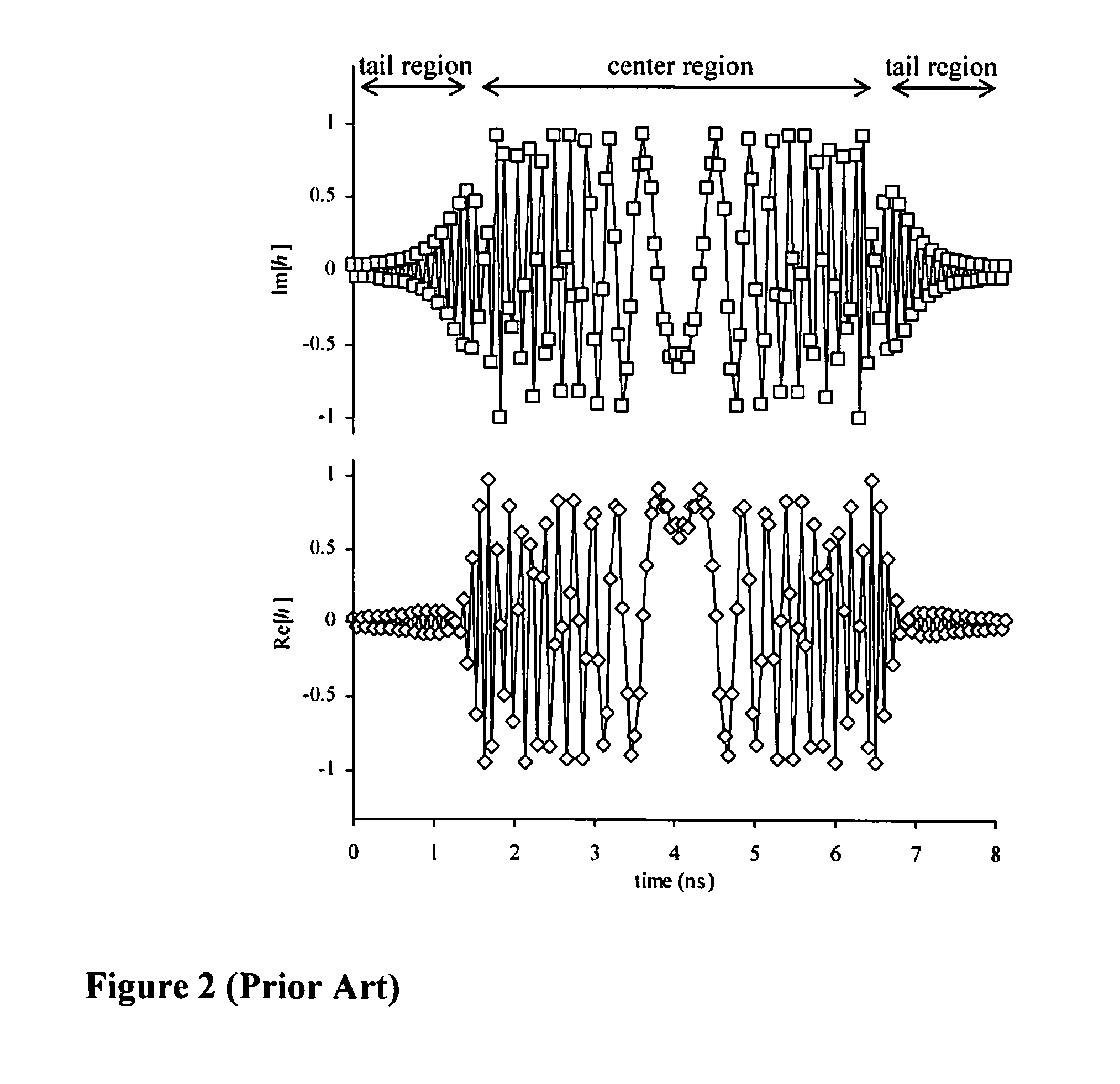
[0035]FIG. 3A is a plot on the complex plane of the tap weight coefficients of FIG. 2, the example of a 10 Gbaud signal over 2000 km NDSF. Each point is a plot of the imaginary part of the coefficient versus the real part. The key feature of FIG. 3A is that most of the points lie close to a circle on the complex plane. Only the tails of the tap weight coefficients, as marked on FIG. 2 and FIG. 3A, deviate significantly from the circle. This circular nature is common to all sets of tap weight coefficients that are designed to compensate for chromatic dispersion. The standard approach to digitization of the tap weights is to digitize the real and imaginary parts independently, to a certain number of binary digits. This is equivalent to moving each point to the closest of a grid of allowed values. The square crosses in FIG. 3B are the allowed digitized values when the complex parts of the coefficients are digitized to 4 binary digits. This is an ine...


PUM


Abstract

A method and apparatus of compensating for compact digital domain chromatic dispersion. The distortion of an optical signal due to chromatic dispersion is compensated by a digital signal processing in the electrical domain, either prior to the optical transmitter or following the receiver. The circular coefficient approximation and sub-band processing reduce the amount of computations to execute a given level of chromatic dispersion compensation compared to a direct finite impulse response filter implementation.

Description

RELATED APPLICATIONS[0001]This utility application claims the benefit of U.S. Provisional Patent Application Ser. No. 60 / 998,184 filed Oct. 9, 2007 and Ser. No. 61 / 015,508 filed Dec. 20, 2007, both by Michael G. Taylor, which are hereby incorporated by reference.BACKGROUND OF THE INVENTION[0002]1. Field of the Invention[0003]This invention relates to optical communications. Specifically, and not by way of limitation, the present invention relates an apparatus and method of compensating for compact digital domain chromatic dispersion.[0004]2. Description of the Related Art[0005]Information has been transmitted over optical fibers since the late 1970s. Discussions in this field are disclosed in “Optical Communication Systems” by John Gowar (Prentice Hall, 2nd ed., 1993) and “Fiber-optic communication systems” by Govind P. Agrawal (Wiley, 2nd ed., 1997), which are herein incorporated by reference. The information is usually in the form of binary digital signals, i.e. logical “1”s and “...

Claims


Application Information

Patent Timeline
IPC IPC(8): H04B10/12
CPCH04B10/25133H04B10/2513H04B10/6972
Inventor TAYLOR, MICHAEL GEORGE
Owner HUAWEI TECH CO LTD
Learn More