
Electrical connection device and connector

Inactive Publication Date: 2009-09-24
ABB (SCHWEIZ) AG
View PDF7 Cites 18 Cited by
  • Summary
  • Abstract
  • Description
  • Claims
  • Application Information

AI Technical Summary

Benefits of technology

[0008]Exemplary embodiments disclosed herein can provide an improved connection device which has sufficient cooling at a contact point of a connector, has a low space requirement and can be joined together and disconnected without any preparatory measures.

Problems solved by technology

However, this means that the contact force in such plug-type connections is lower than is the case in screw-type connections or clamping connections, for example.
A lower contact force in plug-type connections results in increased contact resistance at the contact point, at which a power loss is produced in the event of a current flow owing to the voltage drop.
This results in heating at the contact point of the plug-type connection, which can result in accelerated contact degradation as a result of oxidation or a change to the structure of the contact materials used and ultimately in thermal destruction of the contacts.
One disadvantage is the fact that the cooling laminates have a negative effect on the physical size of the plug and another is the fact that they make insulation of the plug more difficult.
However, one disadvantage is the fact that the coolant channel is also opened, as well as the current path, when the plug-type connection is disconnected, with the result that the liquid coolant needs to be removed before the disconnection.

Method used


Image

  • Electrical connection device and connector
  • Electrical connection device and connector
  • Electrical connection device and connector

Examples


Embodiment Construction

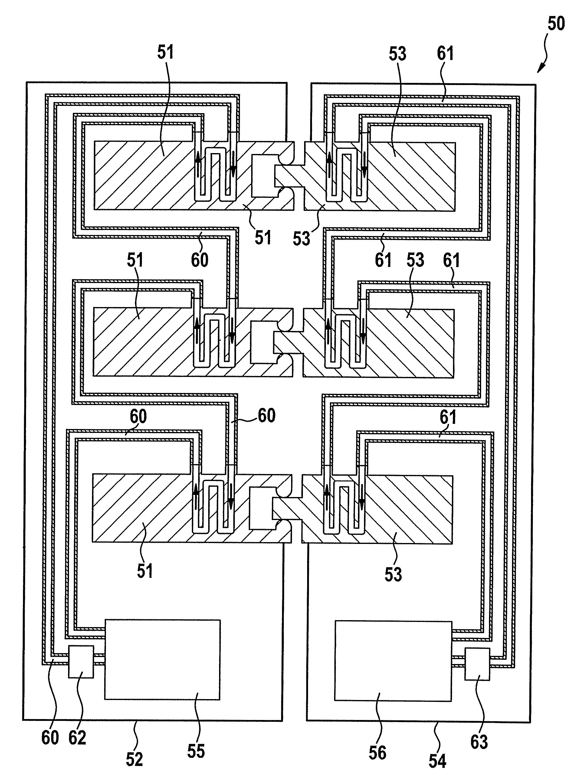
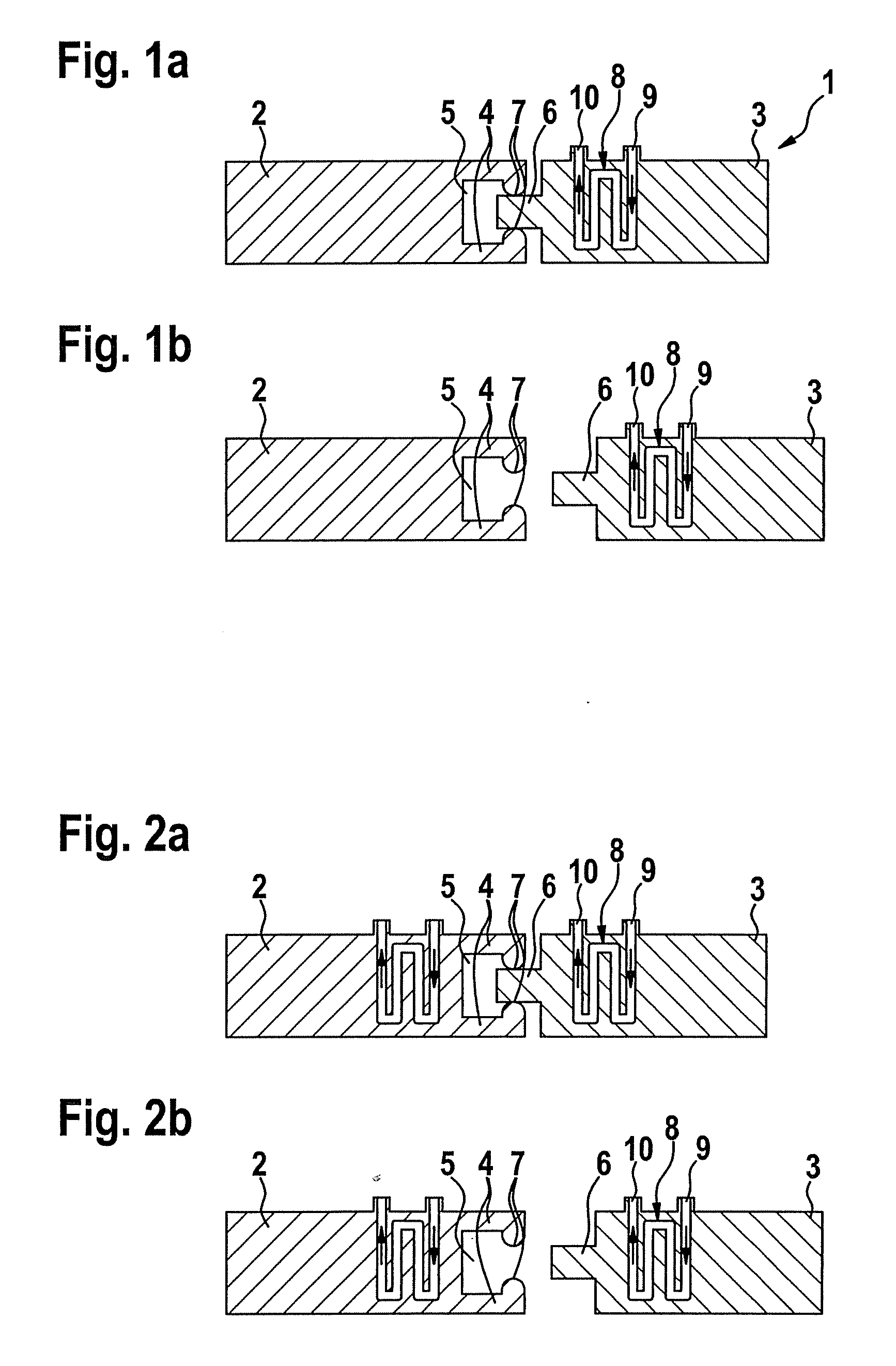
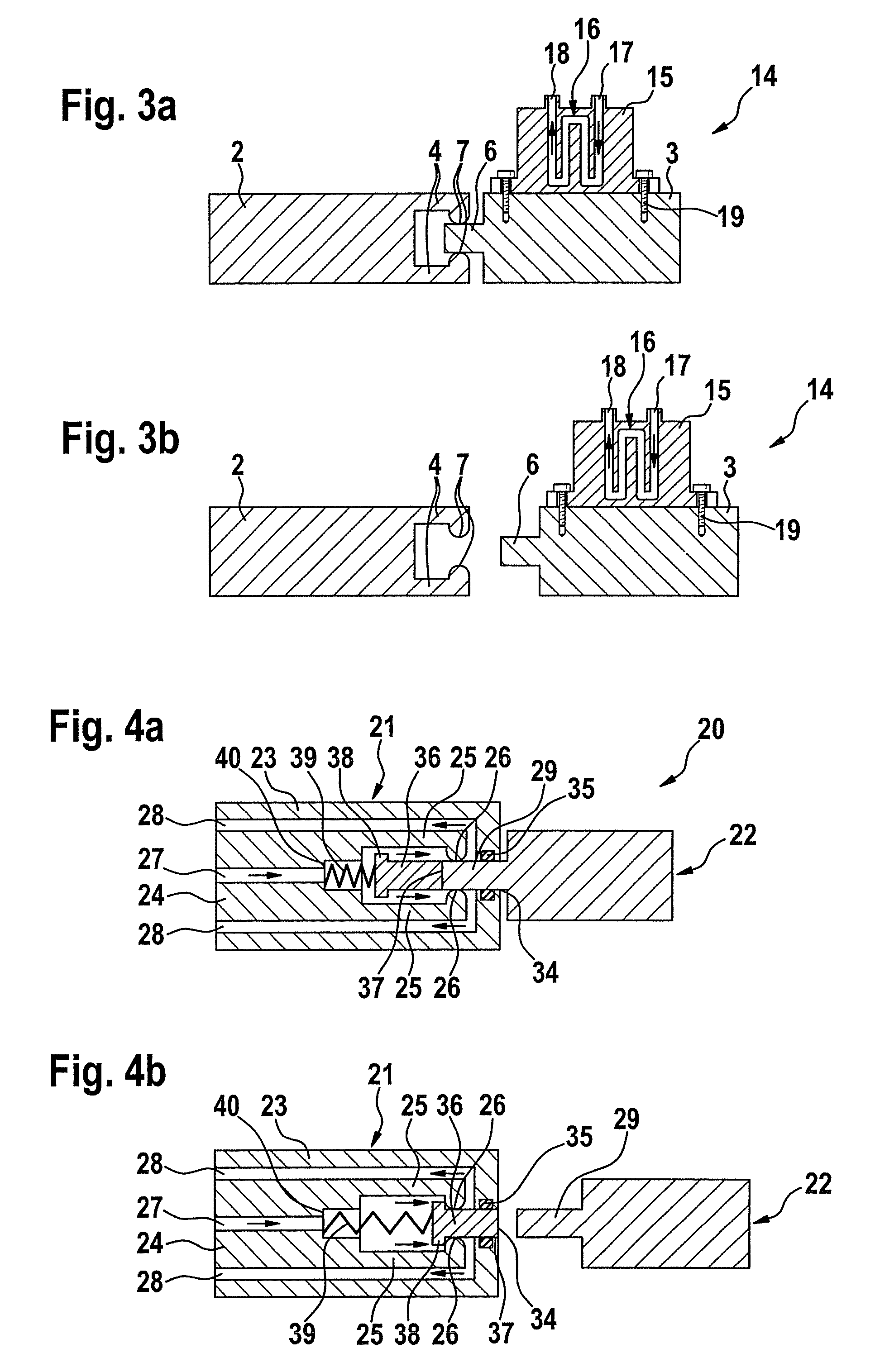
[0021]In accordance with a first aspect, a connection device, in particular a heavy-duty plug-type connection, is provided. The connection device comprises a first connector and a second connector, which each have a contact-making element in order to produce an electrical connection in the connected state of the connectors. The connectors bear against one another at a connection region in the connected state. At least one of the connectors comprises a coolant line with one or more access points for the supply and discharge, respectively, of a coolant. The coolant line is coupled to the contact-making element in order to dissipate heat from a contact point between the contact-making elements. All of the access points of the coolant line are arranged outside of the connection region.

[0022]One aspect of the disclosure provides a coolant line in at least one of the connectors for the connection device, which coolant line is not impaired by the connection device being disconnected and as...


PUM


Abstract

The disclosure relates to a connection device, in particular a heavy-duty plug-type connection, with a first connector and a second connector, which each have a contact-making element in order to produce an electrical connection in the connected state of the connectors; the connectors bearing against one another at a connection region in the connected state; at least one of the connectors comprising a coolant line with one or more access points for the supply and discharge, respectively, of a coolant; the coolant line being provided at the contact-making element in order to dissipate heat from a contact point between the contact-making elements; all of the access points of the coolant line being arranged outside of the connection region.

Description

RELATED APPLICATION[0001]This application claims priority under 35 U.S.C. §119 to European Patent Application No. 08152900.0 filed in Europe on Mar. 18, 2008, the entire content of which is hereby incorporated by reference in its entirety.TECHNICAL FIELD[0002]The disclosure relates to an electrical connection device and to a connector, in particular for producing electrical connections for conducting high currents.BACKGROUND INFORMATION[0003]Electrical plug-type connections have a wide variety of uses. They make it possible to connect electrical devices or assemblies by manually joining together mutually complementary connection elements. In order that said elements can be joined together without a large amount of force being used, the required plug-in forces are designed to be as low as possible. However, this means that the contact force in such plug-type connections is lower than is the case in screw-type connections or clamping connections, for example.[0004]A lower contact forc...

Claims


Application Information

Patent Timeline
IPC IPC(8): H01R13/64H01R29/00
CPCH01R4/28H01R13/02H01R13/52
Inventor SACHER, ROBERTKNAPP, WOLFGANG
Owner ABB (SCHWEIZ) AG
Learn More