Hybrid powertrain and a method for controlling a hybrid powertrain

a hybrid powertrain and hybrid technology, applied in the direction of engine-driven generator propulsion, electric propulsion mounting, transportation and packaging, etc., can solve the problems of affecting system performance, and reducing the service life of hybrid powertrains, so as to achieve smooth and uniform acceleration and deceleration, the effect of increasing the rotation rate rang

Active Publication Date: 2009-09-24
VOLVO LASTVAGNAR AB
View PDF4 Cites 15 Cited by
  • Summary
  • Abstract
  • Description
  • Claims
  • Application Information

AI Technical Summary

Benefits of technology

[0020]The invention is of advantage in that use of the electric machine arrangement to extend a range of rotation rates employable in at least the first gearing ratio is capable of reducing a frequency of gear changes, thereby providing for smoother and more uniform acceleration, and also smoother and more uniform deceleration. Such uniform deceleration is beneficially implemented as regenerative braking.
[0021]Optionally, in the hybrid powertrain, the electric machine arrangement is also employable to extend a rotation rate range provided in a given gearing ratio at both lower rotation rates when accelerating from a standstill or from a preceding gear.

Problems solved by technology

Superficially, such hybrid powertrains would seem to involve additional complexity and potentially added weight which would be deleterious to system performance.
In regard to vehicles equipped with such hybrid powertrains it is conventional contemporary practice to employ combustion engines in such hybrid powertrains to propel the vehicles when higher vehicle speeds have been attained whereat electric motors are not capable of providing any advantage.
Moreover, in crowded buses, people are often standing on account of a lack of seating capacity which places further constraints that acceleration and deceleration of the crowded buses must be smooth and uniform without periods of loss of transmission power propelling the crowded buses.
However, the inventor has found that such contemporary hybrid powertrains are not capable of providing sufficiently smooth and uniform acceleration and deceleration.

Method used


Image

  • Hybrid powertrain and a method for controlling a hybrid powertrain
  • Hybrid powertrain and a method for controlling a hybrid powertrain
  • Hybrid powertrain and a method for controlling a hybrid powertrain

Examples


Embodiment Construction

[0096]In the following, an embodiment of a hybrid powertrain pursuant to the present invention will be described. Thereafter, operation of the hybrid powertrain will be elucidated. Alternative implementations of the hybrid powertrain will then be described.

[0097]While in the following the invention is exemplified in an embodiment of a hybrid powertrain for a vehicle this implies in no way any restriction in regard of the application field of the invention. On the contrary, the invention is usable also in many other application fields as for instance in hybrid powertrains for trains, boats, ships and stationary applications.

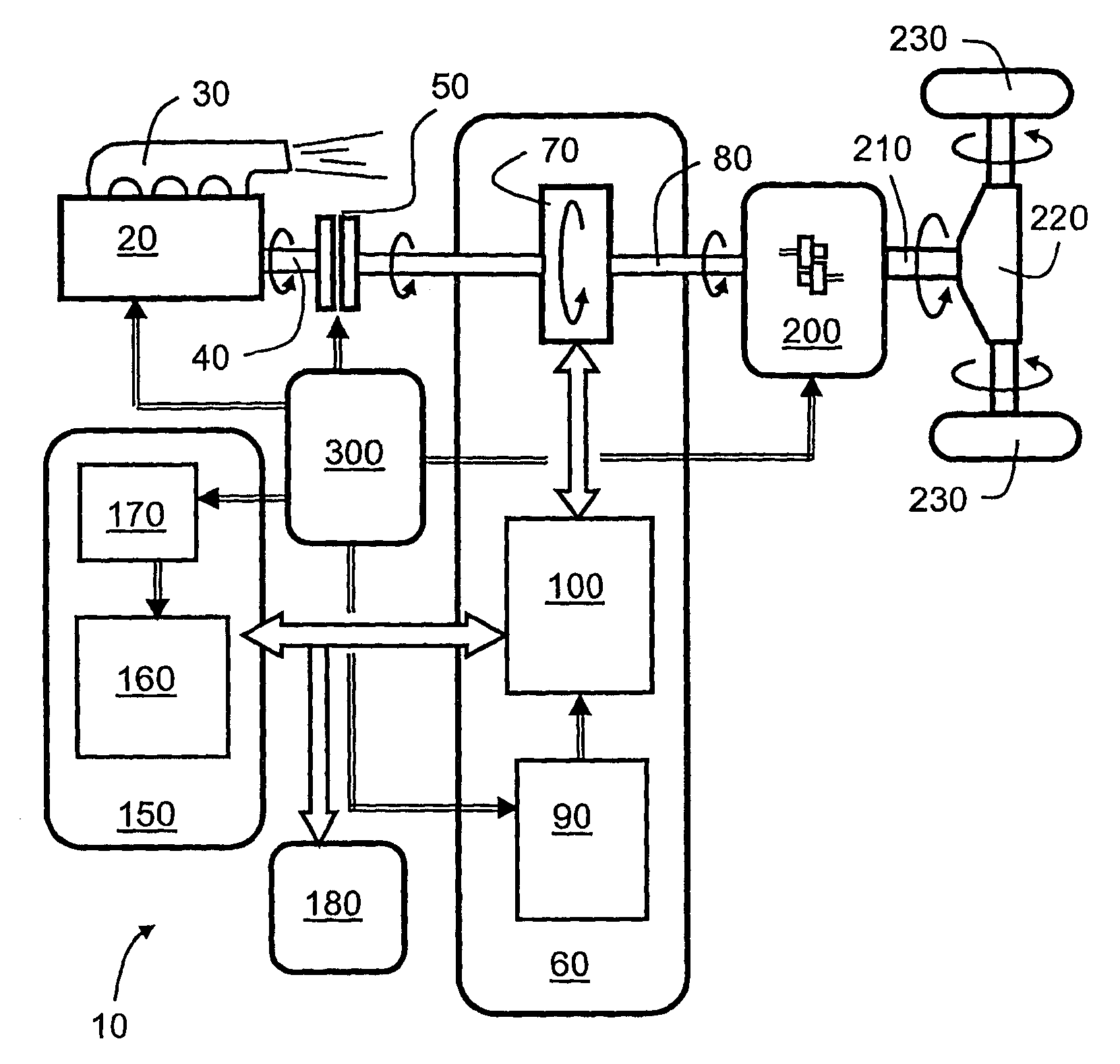
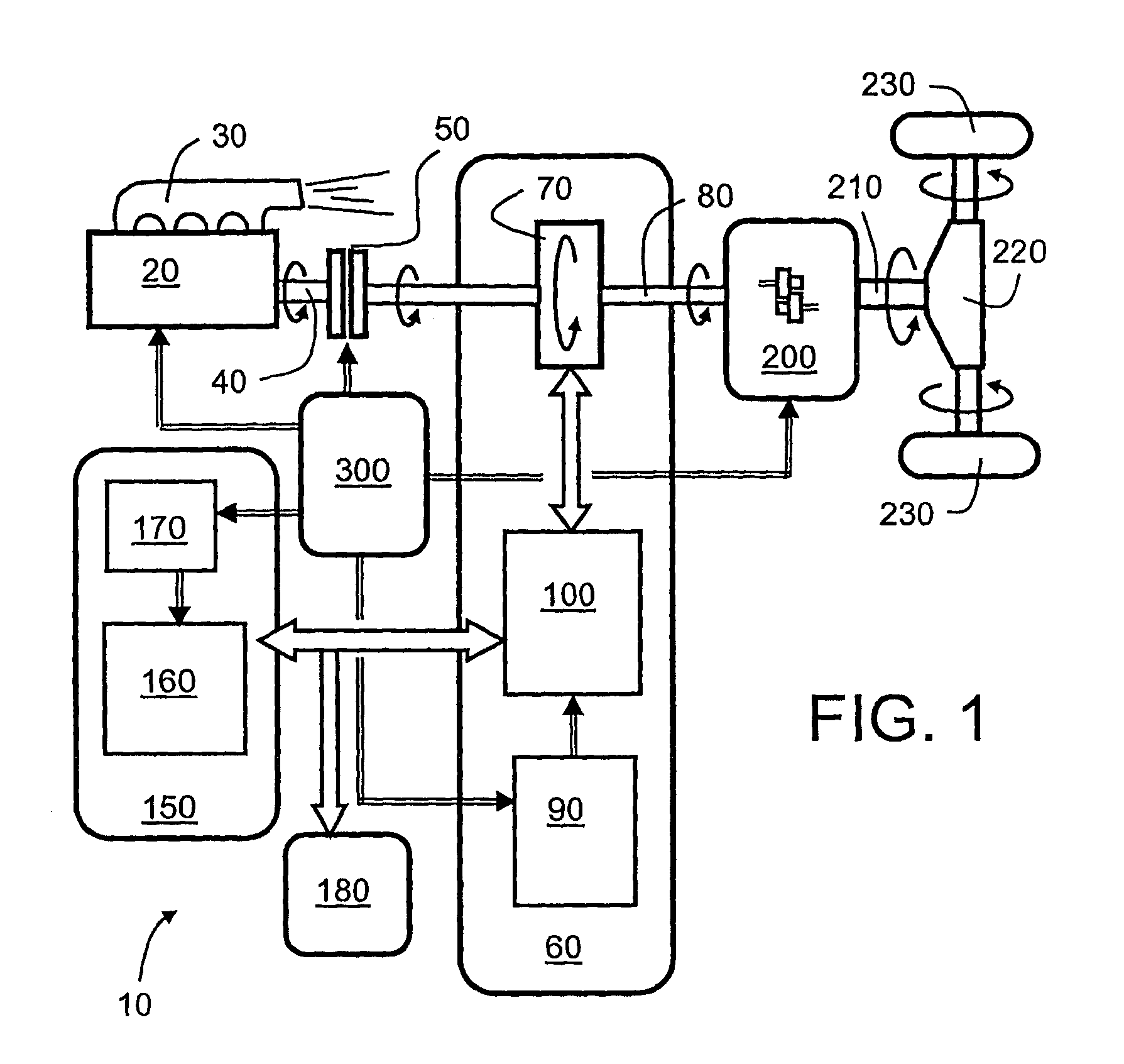
[0098]Referring now to FIG. 1, there is illustrated a hybrid powertrain indicated generally by 10. The hybrid powertrain 10 is designed to include relatively few component parts for ensuring enhanced reliability and compactness. Moreover, many of its parts are adaptations of well proven components used in vehicles throughout the world. However, the hybrid powertra...


PUM


Abstract

A hybrid powertrain includes a combustion engine operable to output rotational power thereat, an electric machine arrangement operable to output rotational power thereat, a gearbox arrangement for receiving rotational power from at least one of the combustion engine and the electric machine arrangement and being operable to couple motive power to a load coupled to the gearbox arrangement. The gearbox arrangement is operable to provide a plurality of gearing ratios. The electric machine arrangement is employable to extend a rotation rate range provided in a given gearing ratio: at higher rotation rates prior to a gear change from said given gearing ratio to a gearing ratio subsequent thereto; or at both lower rotation rates when accelerating from a standstill or from a preceding gear, and at higher rotation rates prior to a gear change from said given gearing ratio to a gearing ratio subsequent thereto.

Description

BACKGROUND AND SUMMARY[0001]The present invention relates to hybrid powertrains for systems, for example for passenger vehicles, buses, trucks, boats, ships, trams, trains and similar. Moreover, the invention also concerns methods of controlling such powertrains, for example with regard to gear change. Furthermore, the present invention also relates to vehicles and similar including such powertrains. Additionally, the present invention relates to software executable on computing hardware for executing the methods of controlling such powertrains.[0002]In recent years, considerable research has been invested in hybrid system technology in order to provide enhanced fuel economy as well as improved motive performance. Hybrid systems include hybrid powertrains, wherein each powertrain usually comprises a combustion engine, an electric machine arrangement, an electrical storage element and a transmission arrangement for coupling at least the electric machine arrangement to a load of the s...

Claims


Application Information

Patent Timeline
Patent Type & Authority Applications(United States)
IPC IPC(8): B60K6/36B60K6/54B60W20/00B60W10/04B60K6/48B60K6/547B60L50/16B60W10/10
CPCB60K6/48B60K6/547B60W10/02Y10T477/23B60W20/00Y02T10/6221B60W10/11B60L1/06B60L15/2054B60L2240/423B60L2240/507B60W10/06B60W10/08B60W20/30Y02T10/72Y02T10/62Y02T10/64
Inventor CARLHAMMAR, LARSCARLSSON, BENNY
Owner VOLVO LASTVAGNAR AB
Why Eureka
Try Eureka