Auditory ossicle prosthesis with variable coupling surfaces

Active Publication Date: 2009-09-24
HEINZ KURZ MEDIZINTECHN
View PDF11 Cites 7 Cited by
  • Summary
  • Abstract
  • Description
  • Claims
  • Application Information

AI Technical Summary

Benefits of technology

[0016]In light of this, the object of the present invention is to improve a middle ear prosthesis of the type described above by the simplest possible technical means and at minimal cost, such that the number of different pro

Problems solved by technology

With the known auditory ossicle prostheses, the sound conduction or signal transmission between the tympanic membrane and the inner ear is often made possible only to a limited extent, since these prostheses are able only to an extremely limited extent to replace the natural anatomical features of the ossicular chain.
During this period, scars and tissue strands form and generate unpredictable forces, which can lead to the prosthesis shifting from its local position.
These pressure peaks can be so high as to result in penetration or extrusion through the tympanic membrane.
Another complication that occurs occasionally is the result of insufficient air in the middle ear cavity and of associated acute or chronic inflammations, tumor formations, adhesions in the region of the tympanic membrane and stiffening of the latter.
However, a disadvantage of these known auditory ossicle prostheses is that, in the event of local medial movements of the tympanic membrane, the inherently rigid tilting of the headplate means that the opposite side of the headplate is also moved out laterally at the same time, as a result

Method used


Image

  • Auditory ossicle prosthesis with variable coupling surfaces
  • Auditory ossicle prosthesis with variable coupling surfaces
  • Auditory ossicle prosthesis with variable coupling surfaces

Examples


Embodiment Construction

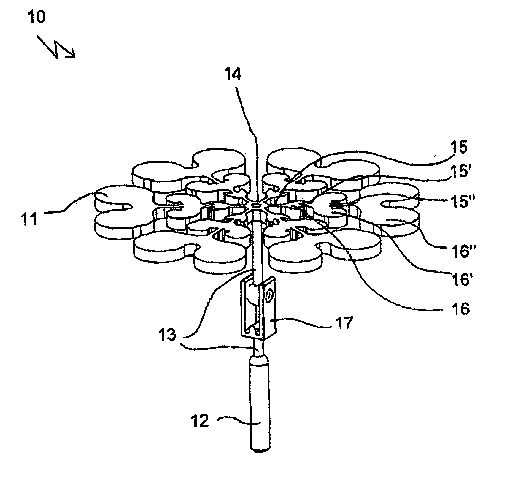
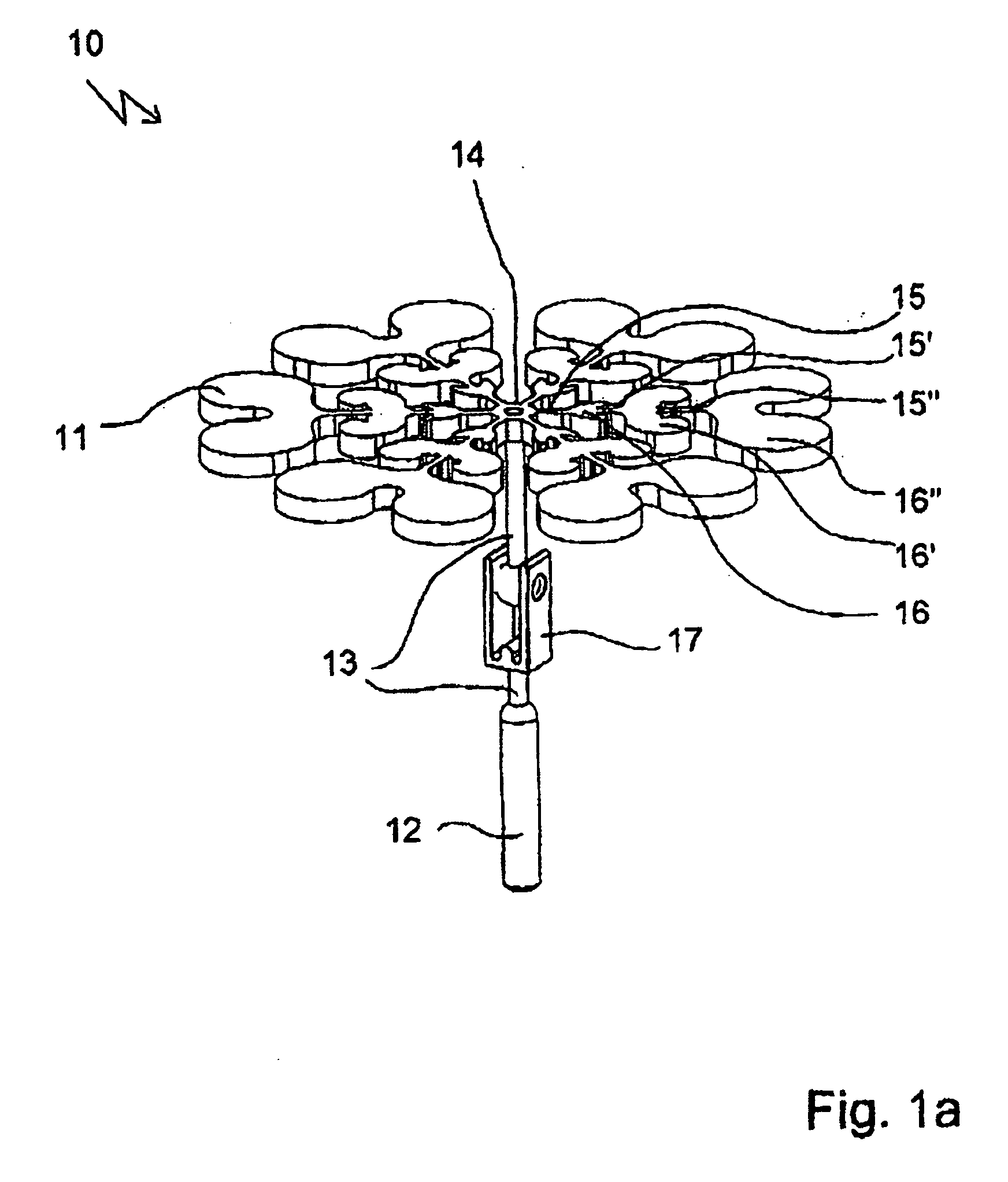
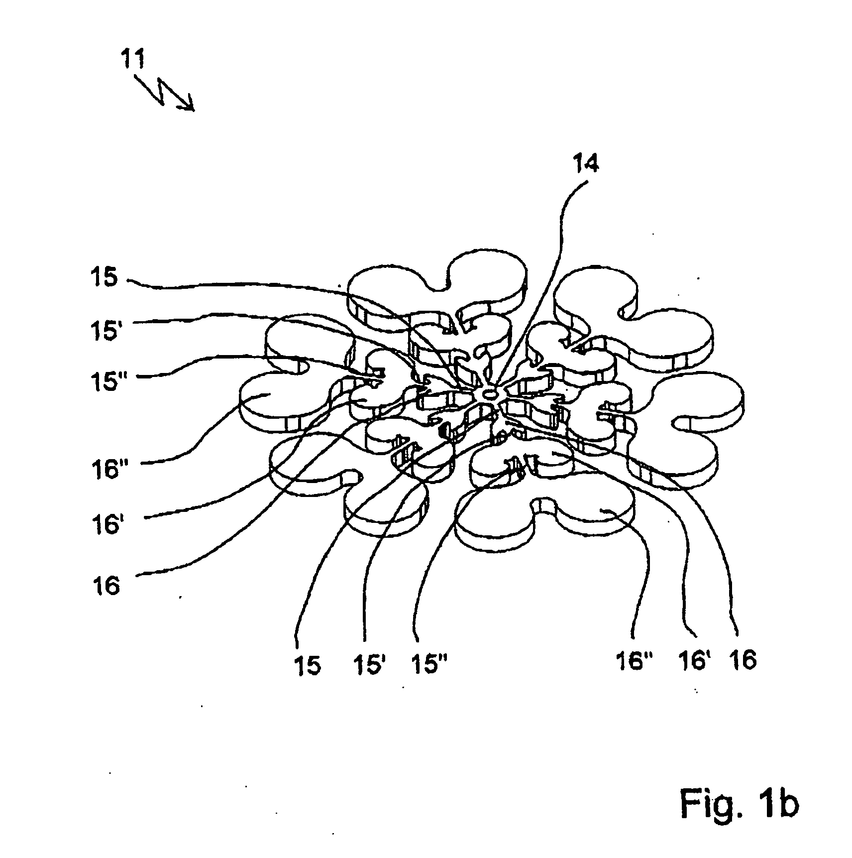
[0070]The auditory ossicle prostheses 10; 20; 30; 40 according to the invention each have, at one end, a plate-shaped first securing element 11; 21; 31 which is designed in the form of a headplate for bearing on the tympanic membrane or as a footplate for bearing on the footplate of the stirrup. At the other end of the auditory ossicle prostheses 10; 20; 30; 40, there is a second securing element 12; 22; 32; 42 for mechanical connection of the prosthesis to a member or parts of a member of the ossicular chain or directly to the inner ear. Arranged between these is a connection element 13; 23; 33 which connects the two securing elements to each other so as to conduct sound and which, in the embodiments shown, is designed in the form of a one-part or multi-part, short or long shaft.

[0071]The plate-shaped first securing element 11; 21; 31 in each case has a radially inner coupling area 14; 24; 34; 54, arranged around its area centroid, for mechanically coupling the first securing eleme...


PUM


Abstract

An auditory ossicle prosthesis (10) which comprises, at one end, a plate-shaped first securing element (11) for bearing on the tympanic membrane or on the footplate of the stirrup, and, at its other end, a second securing element (12) for mechanical connection to the ossicular chain or to the inner ear, and also a connection element (13) that connects the two securing elements so as to conduct sound, wherein the first- securing element has a radially inner coupling area (14) for coupling the first securing element to the connection element, and also a plurality of web elements (15, 15′, 15″) for radial connection of the coupling area to radially outer portions (16, 16′, 16″) of the first securing element, is characterized in that the web elements are of such a geometric configuration, and their material so chosen, that the web elements can be easily broken off and the radially outer portions appended to them detached from the first securing element, such that the external diameter of the first securing element is reduced in this area. This means that the number of different prostheses to be kept ready during an operation can be reduced to a single standard prosthesis, without losing the possibility of optimal adaptation of the prosthesis to the specific case of use.

Description

BACKGROUND OF THE INVENTION[0001]The invention relates to an auditory ossicle prosthesis which replaces or spans at least one member or parts of one member of the ossicular chain, wherein the auditory ossicle prosthesis comprises, at one end, a substantially plate-shaped first securing element for bearing on the tympanic membrane or on the footplate of the stirrup, and, at its other end, a second securing element for mechanical connection to a member or parts of a member of the ossicular chain or to the inner ear, and also a connection element that connects the two securing elements to each other so as to conduct sound, and wherein the plate-shaped first securing element has a radially inner coupling area, arranged centrally especially around the area centroid of the plate-shaped first securing element, for mechanically coupling the first securing element to the connection element, and also a plurality of web elements for radial connection of the radially inner coupling area to radi...

Claims


Application Information

Patent Timeline
IPC IPC(8): A61F2/18
CPCA61F2002/183A61F2/18
Inventor STEINHARDT, UWEKURZ, HEINZ
Owner HEINZ KURZ MEDIZINTECHN
Why Eureka
Try Eureka