Refrigerator and defrost control method thereof

a technology of refrigerator and control method, which is applied in the direction of defrosting, domestic cooling apparatus, etc., can solve the problems of excessive power consumption, reduced heat exchange efficiency of refrigerant passing through the evaporator, and condensation of moisture from the air, and achieve accurate sensing

Inactive Publication Date: 2009-10-01
SAMSUNG ELECTRONICS CO LTD
View PDF1 Cites 18 Cited by
  • Summary
  • Abstract
  • Description
  • Claims
  • Application Information

AI Technical Summary

Benefits of technology

[0011]Therefore, it is an aspect of the embodiments to provide a refrigerator and a defrost control method thereof that are capable of accurately sensing the amount of frost formed on an evaporator based on the change amount of absolute humidity in a storage chamber to perform a defrost operation at the point of time for optimum defrost.

Problems solved by technology

The surface temperature of the evaporator to cool the storage chamber through the refrigeration cycle is lower than the temperature of air in the storage chamber, with the result that moisture condensed from the air in the storage chamber, the temperature of which is relatively high, sticks to the surface of the evaporator, i.e., frost is formed on the evaporator.
With the passage of time, the frost formed on the evaporator thickens, with the result that heat exchange efficiency of the refrigerant passing through the evaporator lowers, and therefore, power consumption increases excessively.
As a result, it is difficult to efficiently defrost the evaporator.
Also, cooling efficiency lowers due to unnecessary repetition of the defrost operation.
Consequently, when a large amount of external moisture is introduced into the storage chamber or a large amount of food is stored in the storage chamber, the amount of moisture in the storage chamber increases, with the result that the amount of frost formed on the evaporator increases.
As a result, the defrost operation is not properly performed, and therefore, the frost formed on the evaporator is not fully removed, which lowers cooling efficiency of the refrigerator.
On the other hand, when the amount of moisture in the storage chamber is not large, the conventional refrigerator, which is constructed to perform the defrost operation for the predetermined integrated operation time of the compressor, although the defrost operation is not necessary when the amount of frost formed on the evaporator is small, unnecessarily frequently performs the defrost operation, with the result that power consumption increases excessively.
Furthermore, high-temperature heat generated from the defrost heater is introduced into the storage chamber, with the result that cooling efficiency is lowered.

Method used


Image

  • Refrigerator and defrost control method thereof
  • Refrigerator and defrost control method thereof
  • Refrigerator and defrost control method thereof

Examples


first embodiment

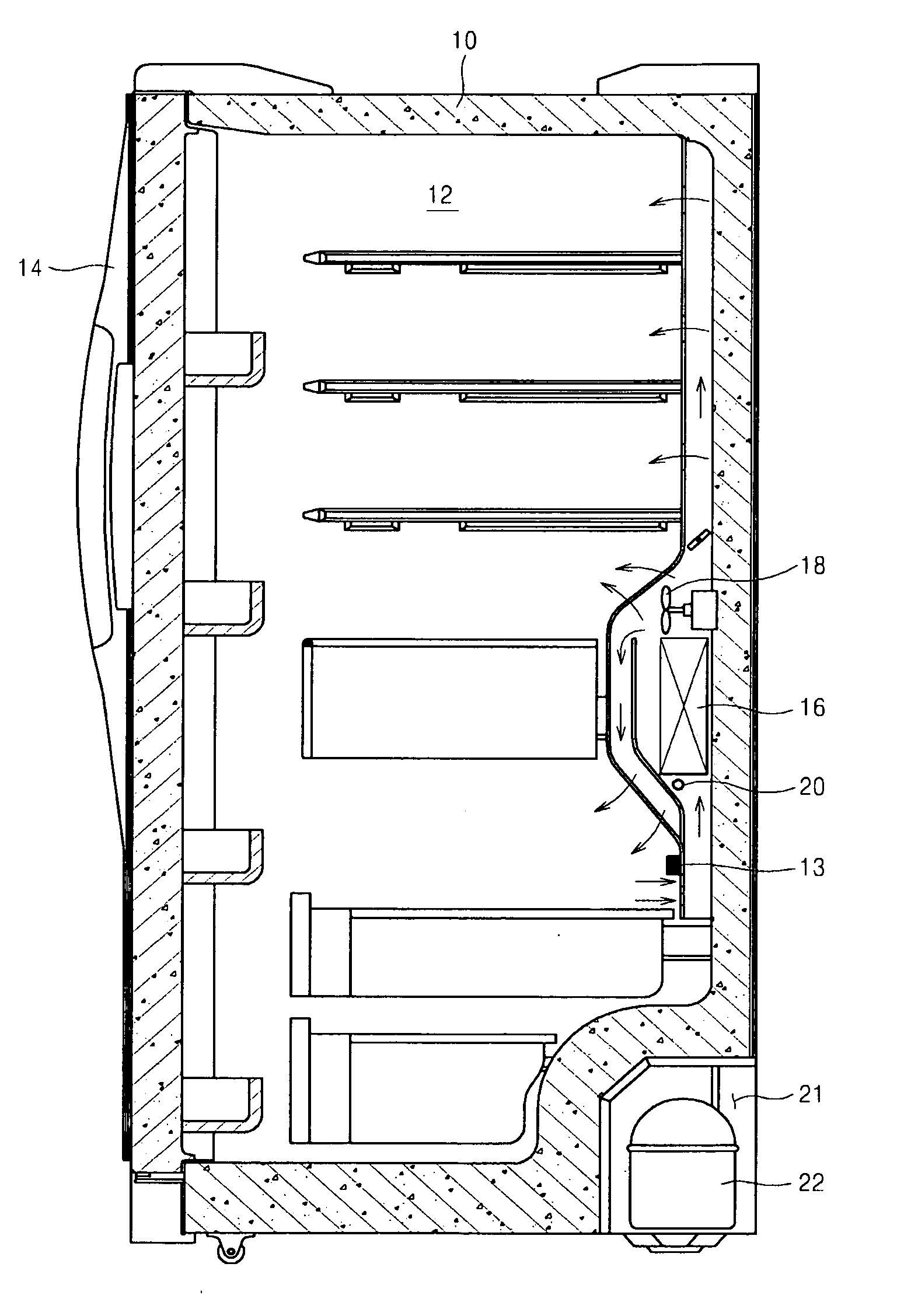
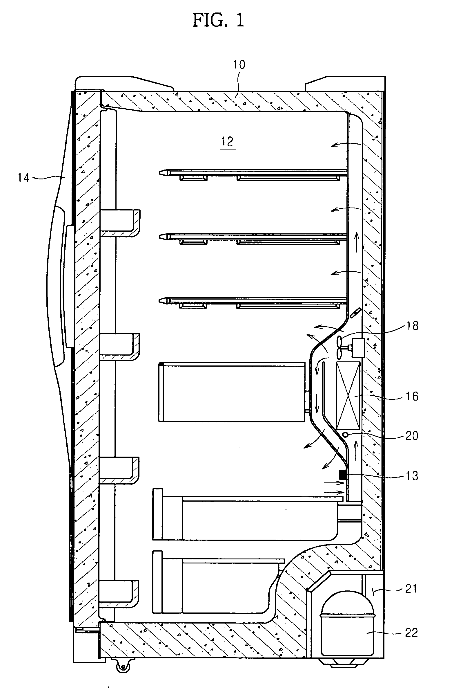
[0047]FIG. 1 is a sectional view illustrating a refrigerator according to a

[0048]Referring to FIG. 1, the refrigerator includes a refrigerator body 10 open at the front thereof, a storage chamber 12 defined in the refrigerator body 10 to store food, and a door 14 hingedly coupled to one side end of refrigerator body 10 to open and close the storage chamber 12.

[0049]At a lower rear of the storage chamber 12 is mounted a humidity sensor 13 to sense absolute humidity in the storage chamber 12.

[0050]Outside the rear of the storage chamber 12 is mounted an evaporator 16 to cool the storage chamber 12. Above the evaporator 16 is mounted a fan 18 to circulate cool air into the storage chamber 12. Below the evaporator 16 is mounted a defrost heater 20 to defrost the evaporator 16.

[0051]Also, a machinery compartment 21, as a separate space, is provided at the lower rear of the refrigerator body 10. In the machinery compartment 21 is mounted a compressor 22.

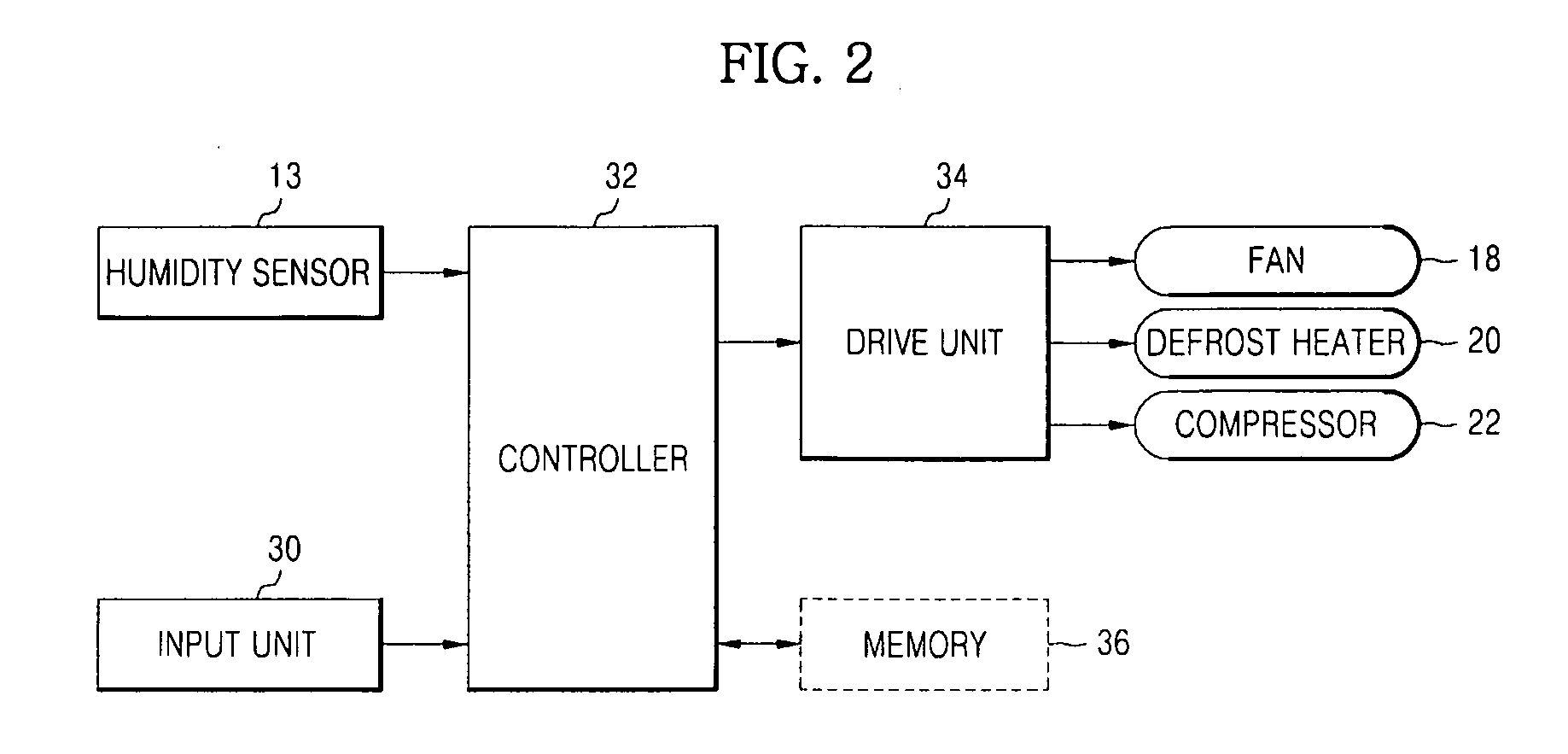
[0052]FIG. 2 is a defrost control b...

second embodiment

[0076]FIG. 5 is a sectional view illustrating a refrigerator according to a Parts of FIG. 5 identical to those of FIG. 1 are denoted by the same numerals and the same titles, and a detailed description thereof will not be given.

[0077]Referring to FIG. 5, a door opening and closing sensor 15 is mounted at the upper front of the storage chamber 12, i.e., at a position where the storage chamber 12 comes into contact with the door 14, to sense the opening and closing of the door 14.

[0078]FIG. 6 is a defrost control block diagram of the refrigerator according to the second embodiment of the present invention. The refrigerator includes a humidity sensor 13, a door opening and closing sensor 15, an input unit 30, a controller 32, a drive unit 34, and a memory 36. Parts of FIG. 6 identical to those of FIG. 2 are denoted by the same numerals and the same titles, and a detailed description thereof will not be given.

[0079]Referring to FIG. 6, the controller 32 calculates the change amount of ...


PUM


Abstract

Disclosed herein are a refrigerator and a defrost control method thereof that are capable of sensing an amount of frost formed on an evaporator based on a change amount of absolute humidity in the refrigerator to control a defrost operation. A defrost control method of a refrigerator including a storage chamber and an evaporator to cool the storage chamber, includes sensing absolute humidity in the storage chamber, determining an estimated amount of frost formed on the evaporator using time segments in which the absolute humidity in the storage chamber decreases, and controlling a defrost operation based on the estimated amount of frost. According to the present embodiments, it is possible to perform the defrost operation at the point of time for optimum defrost, thereby maximizing energy efficiency and cooling efficiency.

Description

CROSS-REFERENCE TO RELATED APPLICATIONS[0001]This application claims the benefit of Korean Patent Application No. 2008-0028705, filed on Mar. 28, 2008 in the Korean Intellectual Property Office, the disclosure of which is incorporated herein by reference.BACKGROUND[0002]1. Field[0003]The present invention relates to a refrigerator and a defrost control method thereof, and, more particularly, to a refrigerator and a defrost control method thereof that are capable of sensing the amount of frost formed on an evaporator based on the change amount of absolute humidity in the refrigerator to control a defrost operation.[0004]2. Description of the Related Art[0005]Generally, a refrigerator is an apparatus that supplies cool air, generated when liquid refrigerant is evaporated to absorb the surrounding heat through a refrigeration cycle in which refrigerant circulates, to a food storage chamber, such as a freezing compartment and a refrigerating compartment, to keep various kinds of food fr...

Claims


Application Information

Patent Timeline
Patent Type & Authority Applications(United States)
IPC IPC(8): F25D21/00F25B39/02F25D17/00F25D21/02
CPCF25B2700/02F25D2700/02F25D2500/04F25D21/02F25D21/004F25D21/08
Inventor HAN, SEONG JOOSHIN, YOUNG SHIKHAN, JEONG SUKIM, SUNG HOONJO, SU HOCHOI, HYEN YOUNGLEE, SANG JUNRYU, O DO
Owner SAMSUNG ELECTRONICS CO LTD
Why Eureka
Try Eureka