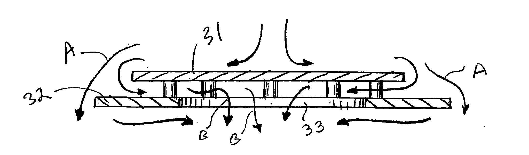
Raised overlapped impingement plate
a technology of impingement plate and raised plate, which is applied in the direction of indirect heat exchangers, corrosion prevention, lighting and heating apparatus, etc., can solve the problems of reducing velocity, affecting accumulating fouling on the surface of tubes, so as to improve the flow of shell-side fluid, reduce fouling, and recover more heat from tube-side fluid.
- Summary
- Abstract
- Description
- Claims
- Application Information
AI Technical Summary
Benefits of technology
Problems solved by technology
Method used
Image

Examples
Embodiment Construction
[0033]For convenience and clarity in describing these embodiments, similar elements or components appearing in different figures will have the same reference numbers.
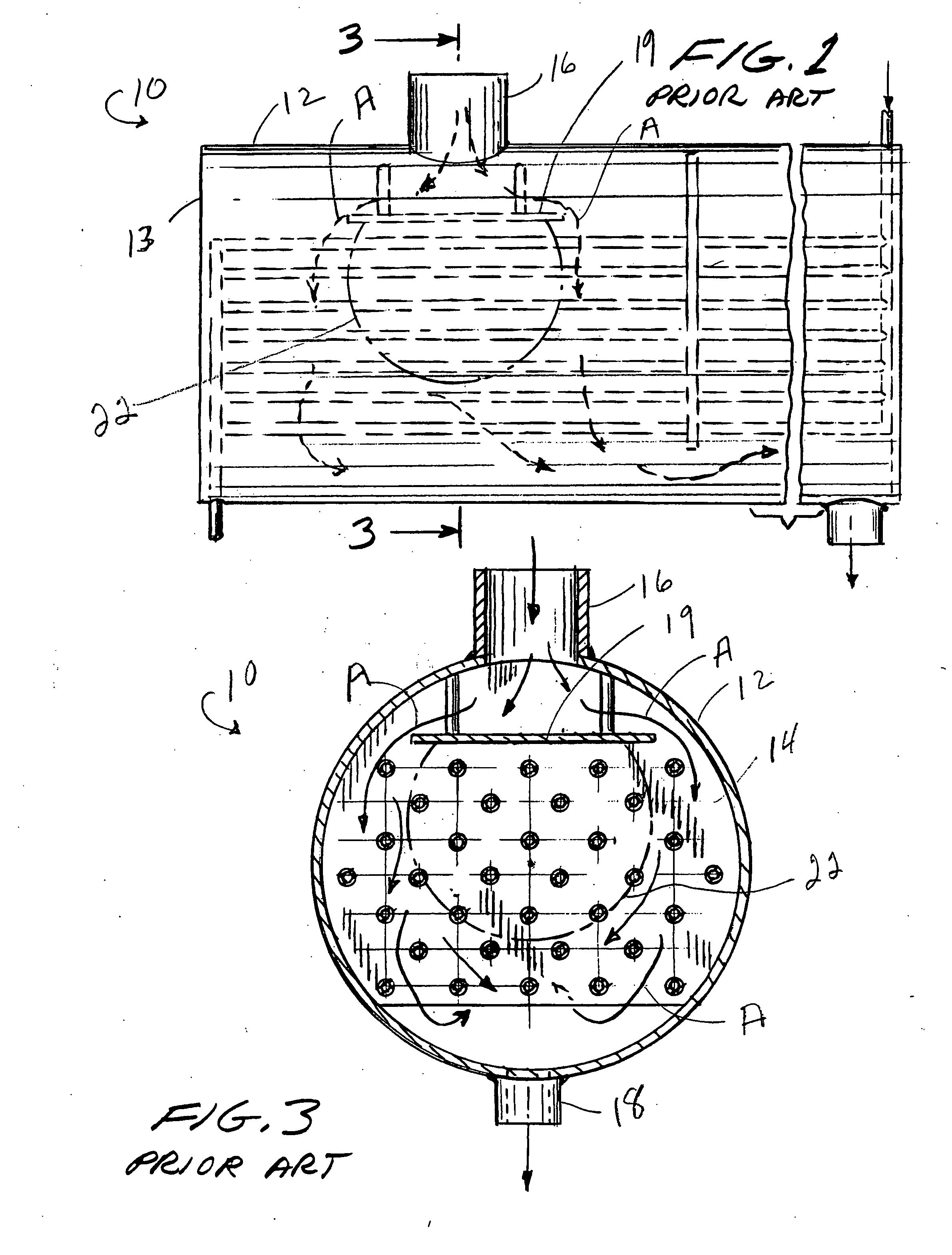
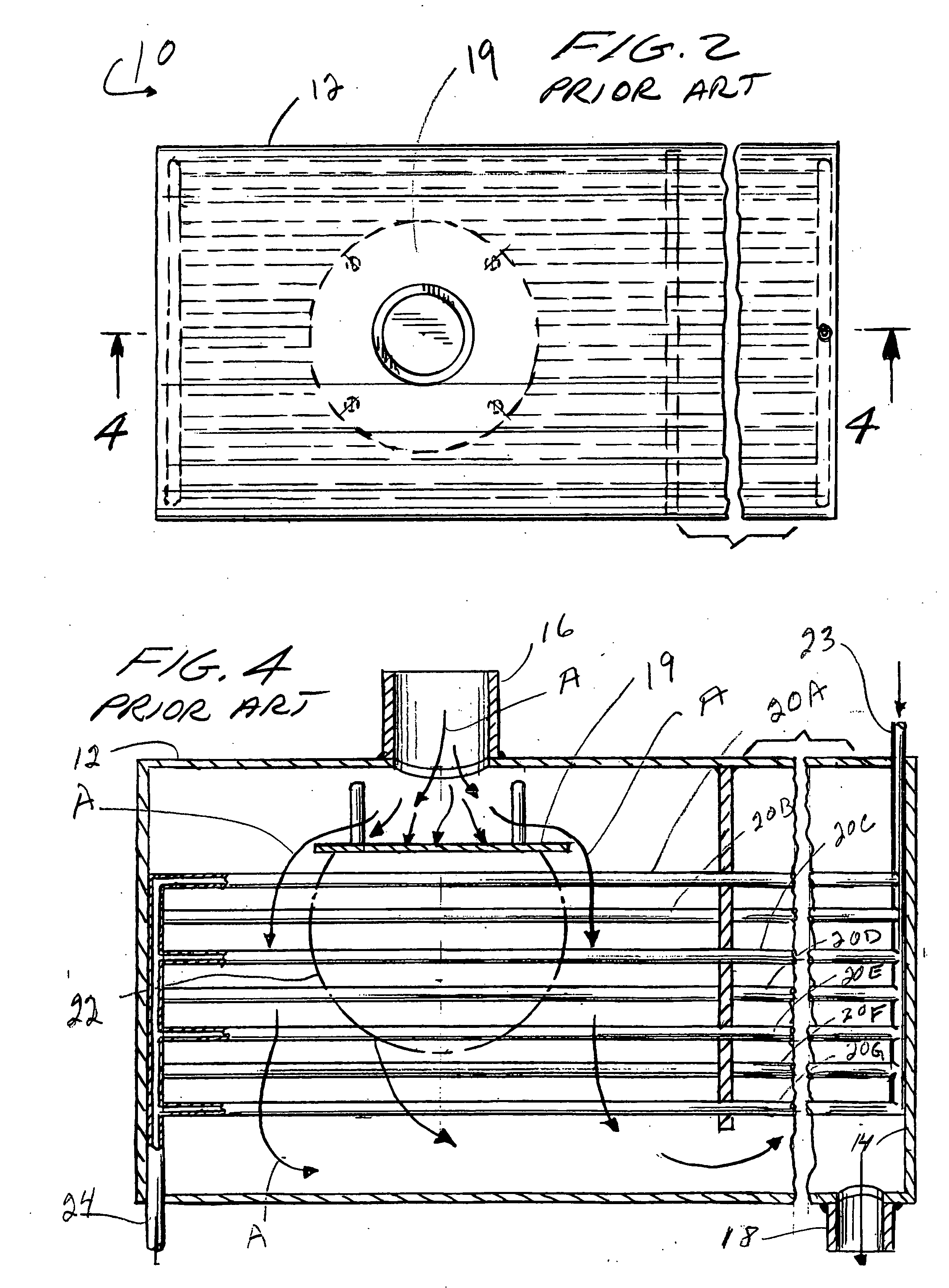
[0034]FIGS. 1-4 illustrate a conventional prior art heat exchanger with a conventional impingement plate situated inward and adjacent of the inlet nozzle and between said inlet nozzle and a bundle of tubes.
[0035]More particularly these figures show a cylindrical heat exchanger 10 formed of a cylindrical shell housing or shell 12 with first end 13 appearing on the left side of FIG. 1 and opposite end 14.
[0036]As shown in these figures, housing 12 has a principal or typical fluid inlet 16 and an outlet 18. Fluid flowing from inlet 16 to outlet 18 initially strikes impingement plate 19, and then follows primarily the path indicated by long arrows A, flowing between, around and engaging the outer surfaces of tubes 20A-20G.
[0037]Arrows A indicate how the fluid from inlet 16 tends to not flow in the fouling area 22 shown in t...
PUM
 Abstract
Description
Claims
Application Information
 - R&D
- Intellectual Property
- Life Sciences
- Materials
- Tech Scout
- Unparalleled Data Quality
- Higher Quality Content
- 60% Fewer Hallucinations
Browse by: Latest US Patents, China's latest patents, Technical Efficacy Thesaurus, Application Domain, Technology Topic, Popular Technical Reports.
© 2025 PatSnap. All rights reserved.Legal|Privacy policy|Modern Slavery Act Transparency Statement|Sitemap|About US| Contact US: help@patsnap.com