Fluid bed reactor

Active Publication Date: 2011-05-19
REC SILICON
View PDF53 Cites 40 Cited by
  • Summary
  • Abstract
  • Description
  • Claims
  • Application Information

AI Technical Summary

Benefits of technology

Fluidized bed reactor systems for production of high purity silicon-coated particles are disclosed. Disclosed embodiments of fluidized bed reactor systems reduce fouling of the nozzle opening and reactor walls compared to

Problems solved by technology

A common problem in fluidized bed reactors is fouling of the nozzle and surrounding reactor walls as silicon deposits form around the nozzle opening and on the walls.
Silicon-bearing gas also may decompose an

Method used


Image

  • Fluid bed reactor
  • Fluid bed reactor
  • Fluid bed reactor

Examples


Example

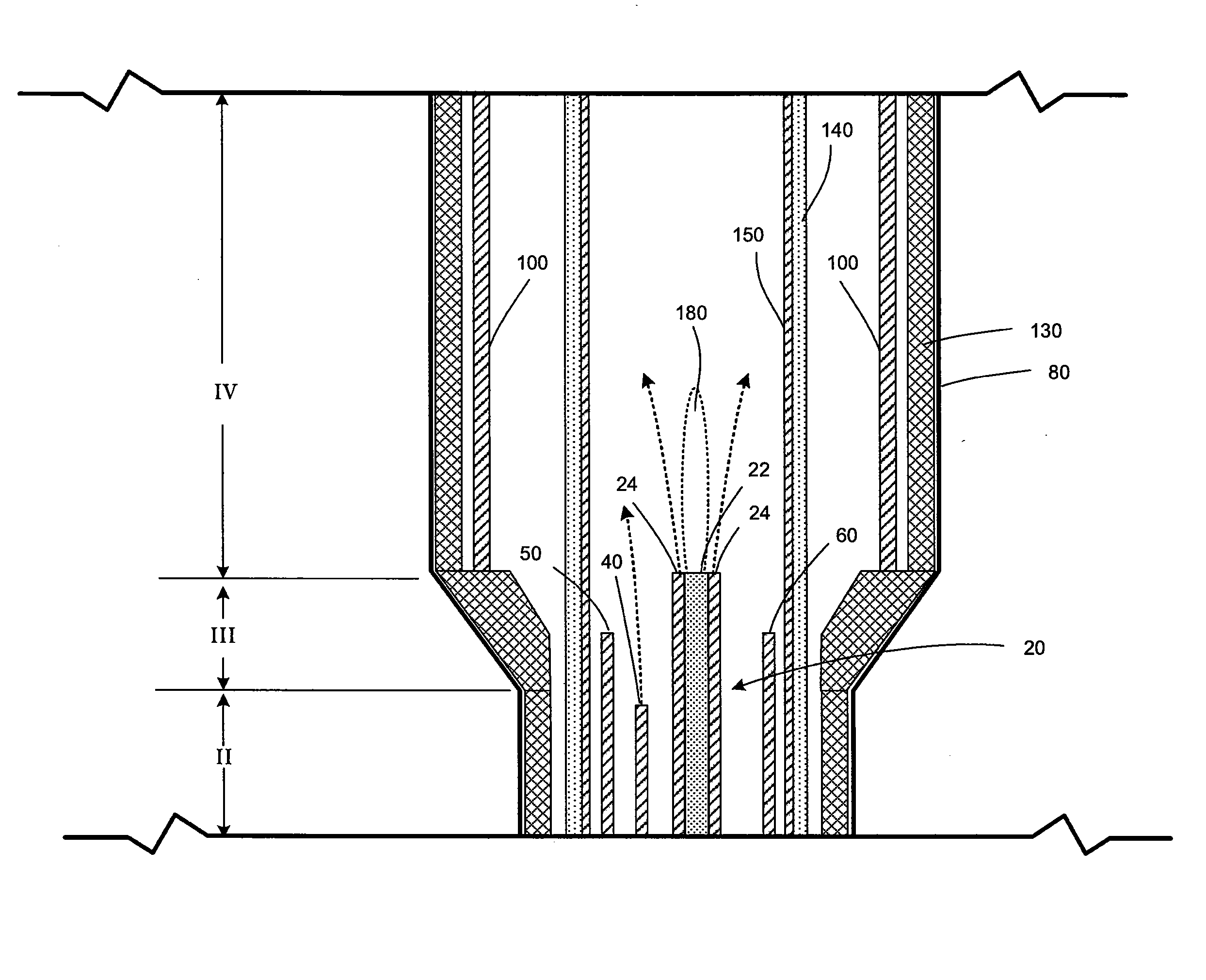
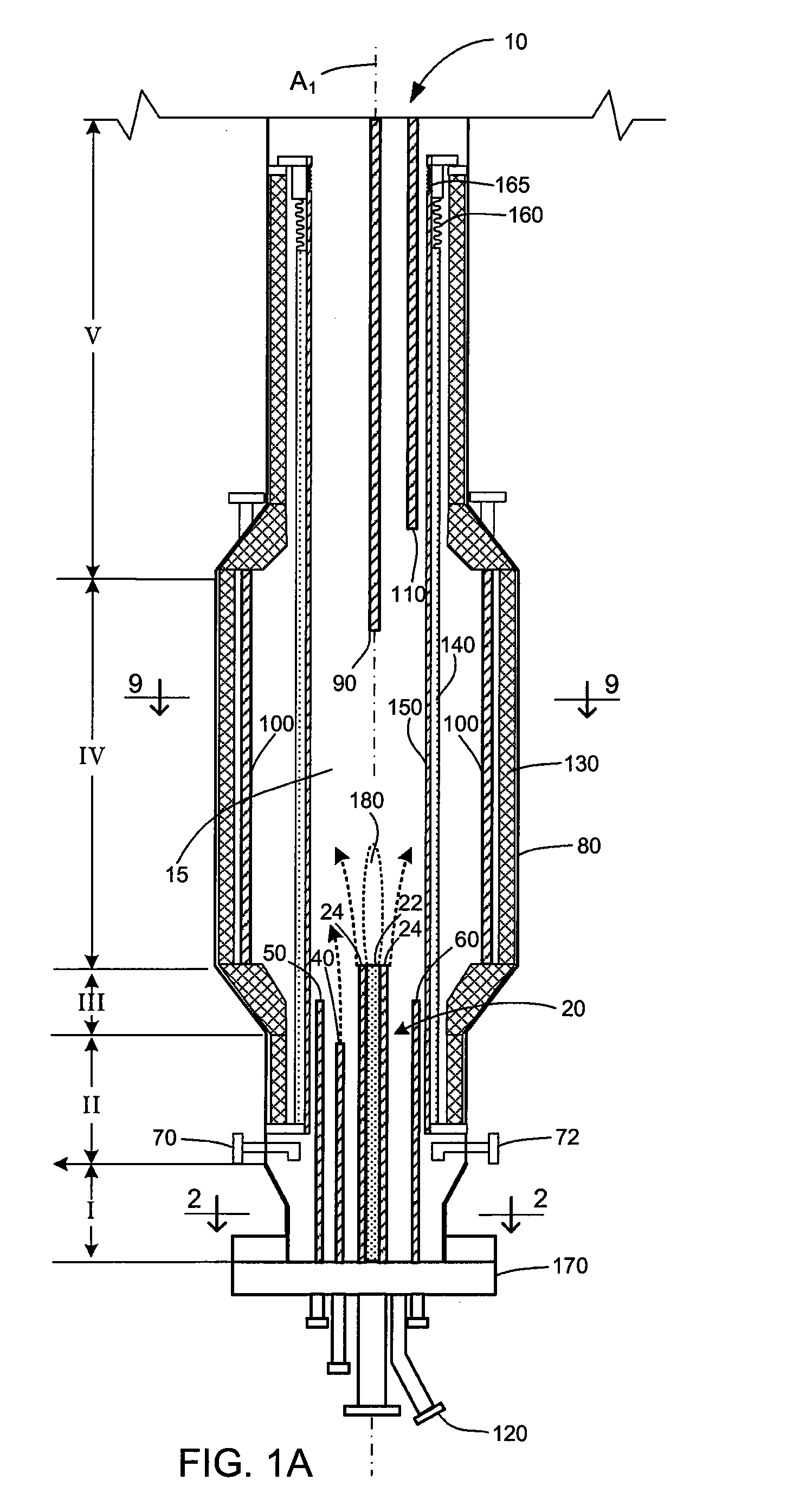
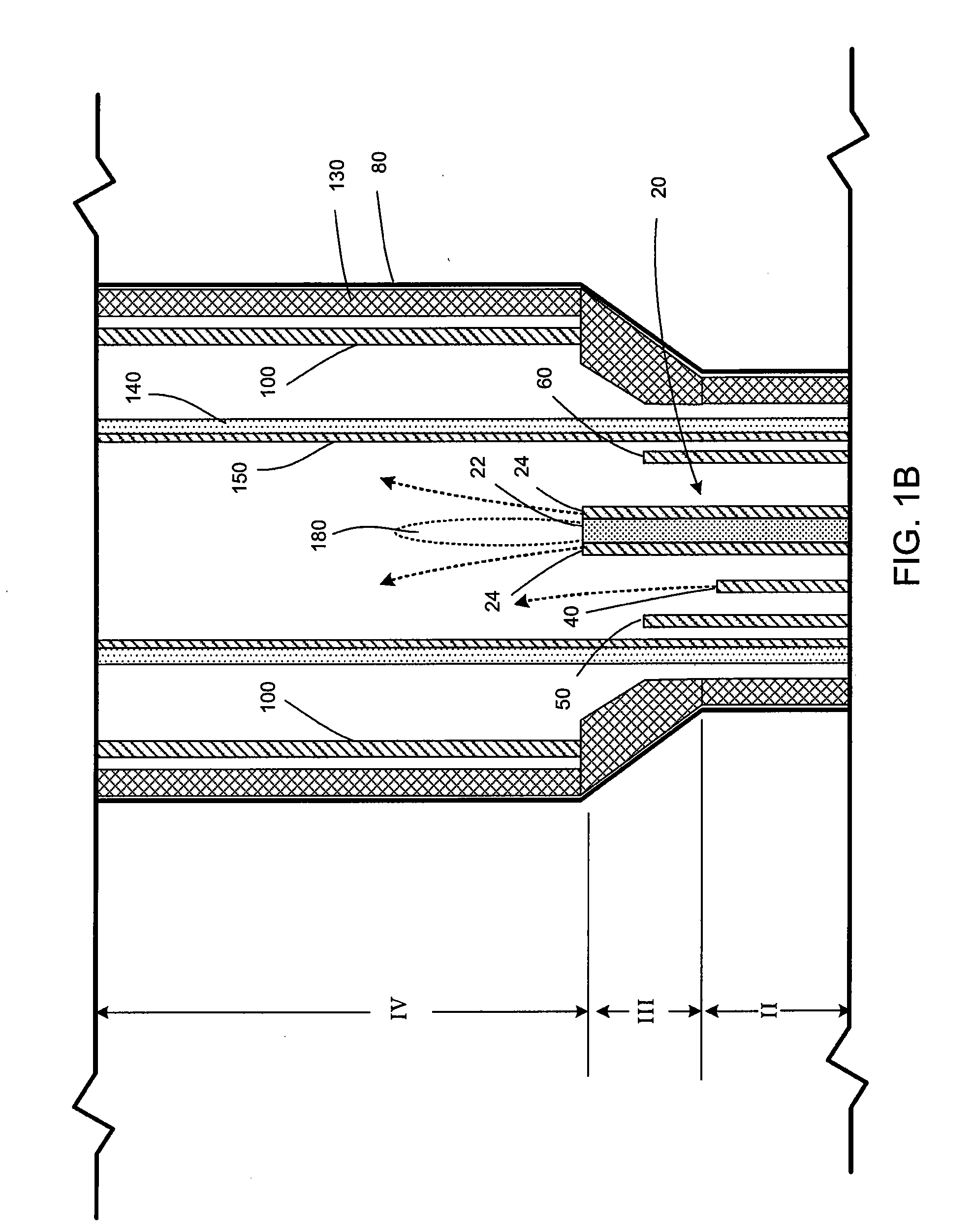
Disclosed herein are fluidized bed reactor systems for the formation of polysilicon by pyrolytic decomposition of a silicon-bearing gas and deposition of silicon onto fluidized silicon particles or other seed particles (e.g., silica, graphite, or quartz particles). Also disclosed are methods for operating the fluidized bed reactor systems.

Silicon is deposited on particles in a reactor by decomposition of a silicon-bearing gas selected from the group consisting of silane (SiH4), disilane (Si2H6), higher order silanes (SinH2n+2), dichlorosilane (SiH2Cl2), trichlorosilane (SiHCl3), silicon tetrachloride (SiCl4), dibromosilane (SiH2Br2), tribromosilane (SiHBr3), silicon tetrabromide (SiBr4), diiodosilane (SiH2I2), triiodosilane (SiHI3), silicon tetraiodide (SiI4), and mixtures thereof. The silicon-bearing gas may be mixed with one or more halogen-containing gases, defined as any of the group consisting of chlorine (Cl2), hydrogen chloride (HCl), bromine (Br2), hydrogen bromide (HBr), io...


PUM

PropertyMeasurementUnit
Temperatureaaaaaaaaaa

Abstract

Fluidized bed reactor systems for producing high purity silicon-coated particles are disclosed. A vessel has an outer wall, an insulation layer inwardly of the outer wall, at least one heater positioned inwardly of the insulation layer, a removable concentric liner inwardly of the heater, a central inlet nozzle, a plurality of fluidization nozzles, at least one cooling gas nozzle, and at least one product outlet. The system may include a removable concentric sleeve inwardly of the liner. In particular systems the central inlet nozzle is configured to produce a primary gas vertical plume centrally in the reactor chamber to minimize silicon deposition on reactor surfaces.

Description

FIELDThe present disclosure relates to pyrolytic decomposition of a silicon-bearing gas in a fluidized bed to produce silicon-coated particles.BACKGROUNDPyrolytic decomposition of silicon-bearing gas in fluidized beds is an attractive process for producing polysilicon for the photovoltaic and semiconductor industries due to excellent mass and heat transfer, increased surface for deposition, and continuous production. Compared with a Siemens-type reactor, the fluidized bed reactor offers considerably higher production rates at a fraction of the energy consumption. The fluidized bed reactor can be continuous and highly automated to significantly decrease labor costs.A common problem in fluidized bed reactors is fouling of the nozzle and surrounding reactor walls as silicon deposits form around the nozzle opening and on the walls. Silicon-bearing gas also may decompose and deposit silicon within the nozzle if the temperature is sufficiently high. Another common problem is contamination...

Claims


Application Information

Patent Timeline
IPC IPC(8): H01L21/20C23C16/24
CPCC23C16/24C23C16/4404C23C16/4417Y10S118/05C23C16/45576H01L21/02532H01L21/0262C23C16/442
Inventor OSBORNE, E. WAYNESPANGLER, MICHAEL V.ALLEN, LEVI C.GEERTSEN, ROBERT J.EGE, PAUL E.STUPIN, WALTER J.ZEININGER, GERALD
Owner REC SILICON
Why Eureka
Try Eureka