
Airfoil-Shaped Micro-Mixers for Reducing Fouling on Membrane Surfaces

a micro-mixer and airfoil technology, applied in membrane technology, membranes, transportation and packaging, etc., can solve the problems of increasing operation costs, increasing pressure drop along the channel, reducing the efficiency of filtration, etc., to reduce the fouling of the membrane surface, enhance the mixing effect, and minimize the additional pressure drop

Active Publication Date: 2010-05-13
NAT TECH & ENG SOLUTIONS OF SANDIA LLC
View PDF1 Cites 39 Cited by
  • Summary
  • Abstract
  • Description
  • Claims
  • Application Information

AI Technical Summary

Benefits of technology

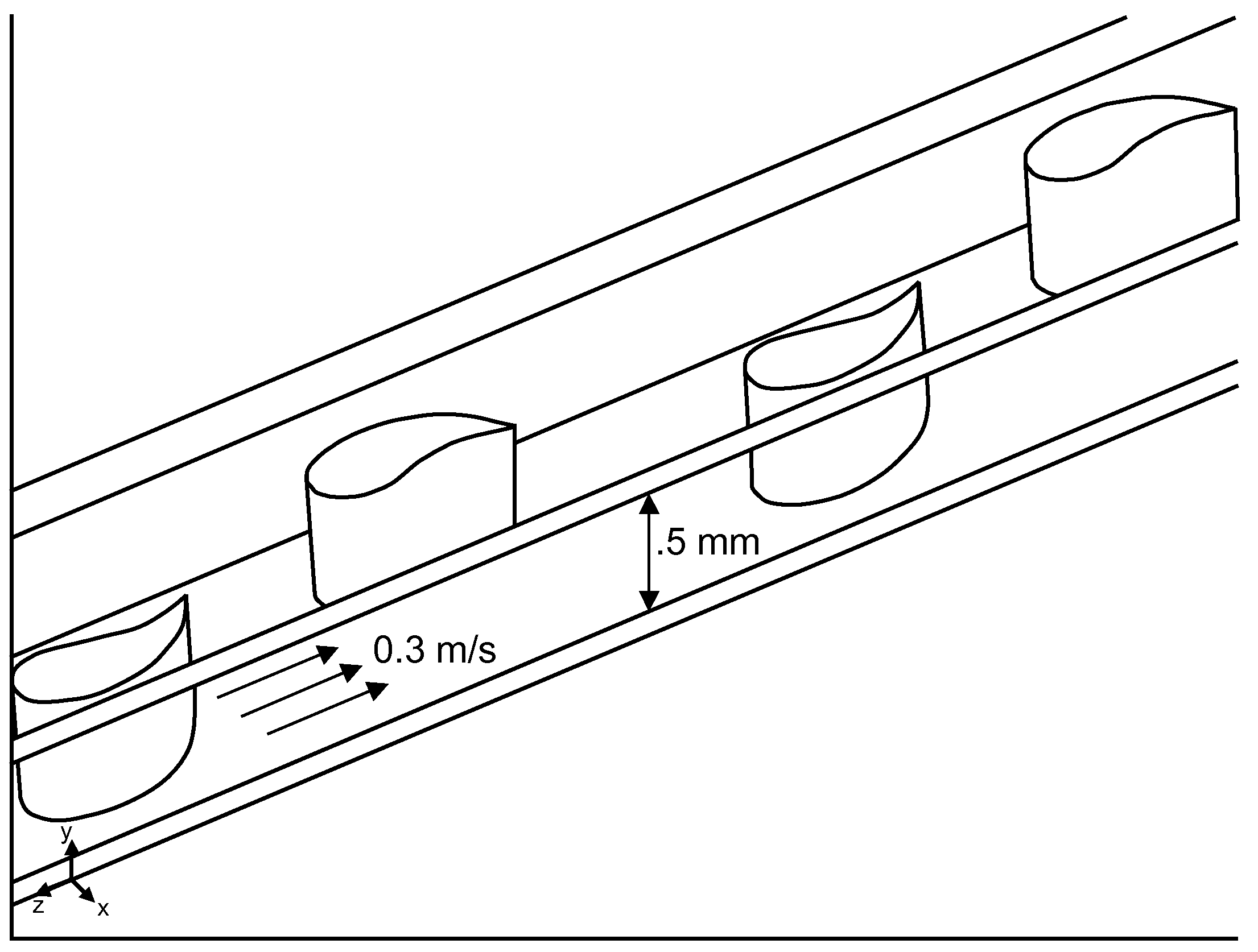
[0008]An array of airfoil-shaped micro-mixers that enhances fluid mixing within permeable membrane channels, such as used in reverse-osmosis filtration units, while minimizing additional pressure drop. The enhanced mixing reduces fouling of the membrane surfaces. The airfoil-shaped micro-mixer can also be coated with or comprised of biofouling-resistant (biocidal / germicidal) ingredients.

Problems solved by technology

The major problems associated with membrane-based separation processes include fouling from organic and inorganic contaminants and high pressure loss, which decrease the efficiency of the filtration, while increasing operation costs.
However, these designs suffer from increased pressure drop along the channel, and from regions of low flow and stagnation directly downstream of the cylindrical insert.

Method used


Image

  • Airfoil-Shaped Micro-Mixers for Reducing Fouling on Membrane Surfaces
  • Airfoil-Shaped Micro-Mixers for Reducing Fouling on Membrane Surfaces
  • Airfoil-Shaped Micro-Mixers for Reducing Fouling on Membrane Surfaces

Examples


Embodiment Construction

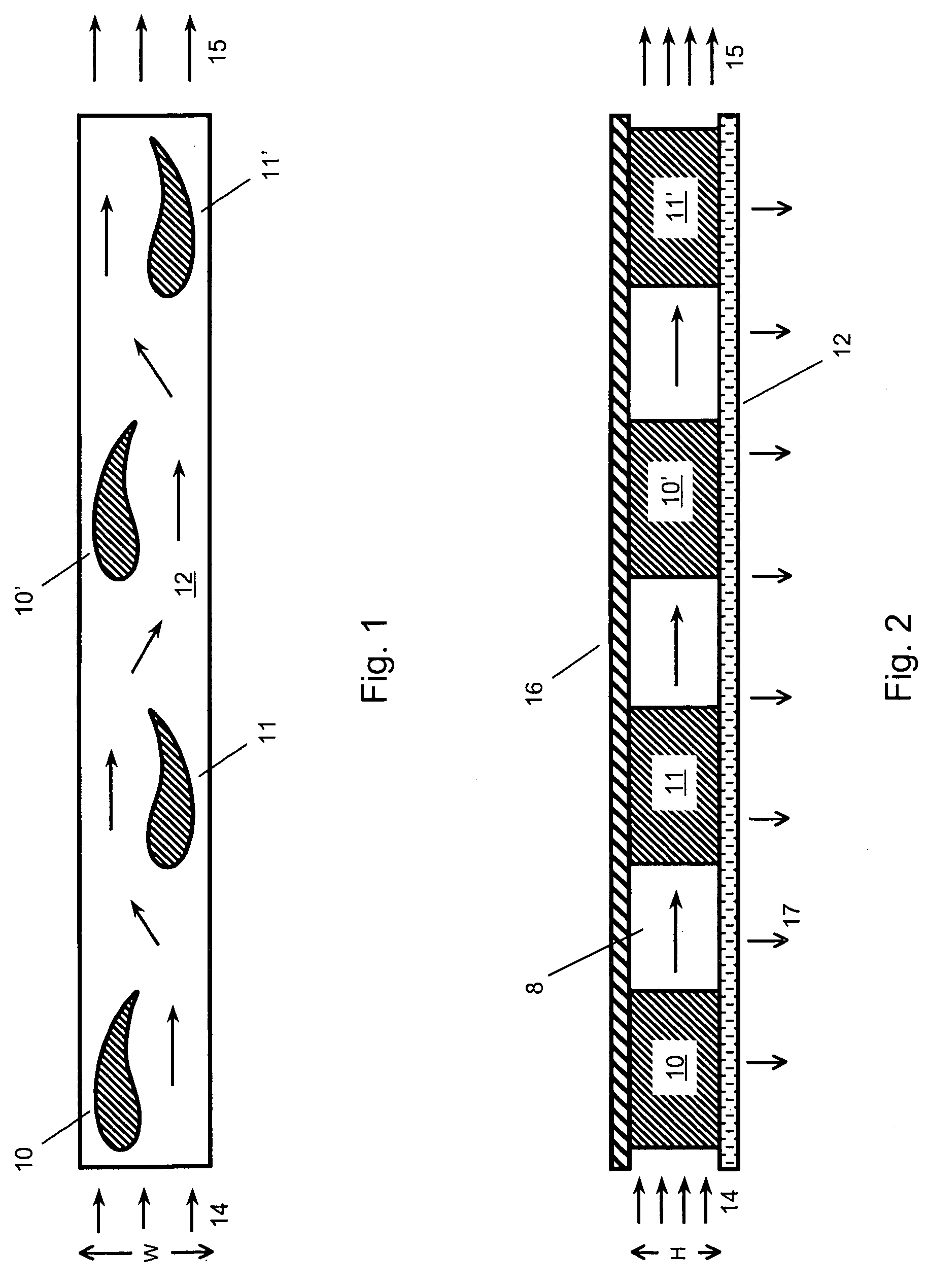
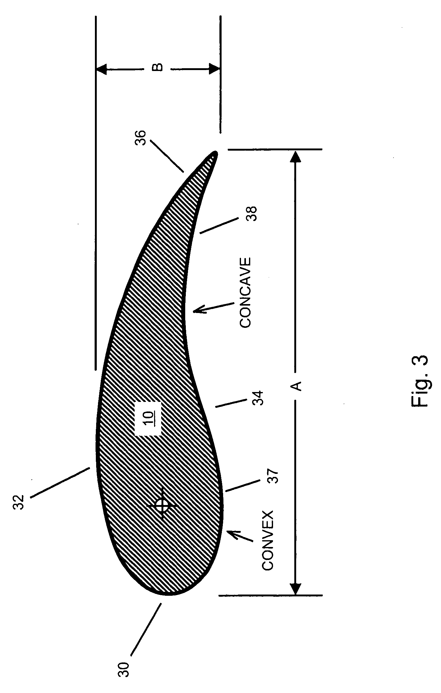
[0027]FIG. 1 shows a schematic top view of a staggered array of alternating airfoil-shaped micro-mixers 10, 10′, 11, 11′ disposed on a membrane substrate 12. FIG. 2 shows a side view of the same arrangement. Micro-channel 8 has channel height=H, and is bounded on the lower surface by a permeable membrane 12 (e.g., a RO membrane), and on the top surface by an upper surface 16. A typical micro-channel height, H, ranges from 0.1 to a few mm's. Upper surface 16 can be permeable or non-permeable surface. Process fluid (e.g., salt water) enters at the left end 14, flows from left to right through micro-channel 8 in a zig-zag path around the micro-mixers, eventually exiting at the right end 15. A portion (17) of the process fluid permeates through the permeable membrane 12. Micro-mixers 10, 10′, 11, 11′ can be disposed only on the lower membrane surface 12; or only on the upper surface 16; or to both. Micro-mixers 10, 10′, 11, 11′ function as fixed ‘posts’ or ‘spacers’ or ‘vanes’, and have...


PUM


Abstract

An array of airfoil-shaped micro-mixers that enhances fluid mixing within permeable membrane channels, such as used in reverse-osmosis filtration units, while minimizing additional pressure drop. The enhanced mixing reduces fouling of the membrane surfaces. The airfoil-shaped micro-mixer can also be coated with or comprised of biofouling-resistant (biocidal / germicidal) ingredients.

Description

FEDERALLY SPONSORED RESEARCH[0001]The United States Government has rights in this invention pursuant to Department of Energy Contract No. DE-AC04-94AL85000 with Sandia Corporation.CROSS-REFERENCE TO RELATED APPLICATIONS[0002]NoneBACKGROUND OF THE INVENTION[0003]The present invention relates generally to a method and apparatus for reducing fouling on permeable membrane surfaces, such as Reverse Osmosis (RO) desalination membranes.[0004]Membrane-based separation processes, such as reverse osmosis and ultra- or nano-filtration, are commonly used in industrial applications, such as: desalination, wastewater treatment, and power generation. The major problems associated with membrane-based separation processes include fouling from organic and inorganic contaminants and high pressure loss, which decrease the efficiency of the filtration, while increasing operation costs.[0005]Localized fouling from mineral deposition and biofilms have been correlated with “dead zones” of low flow and low ...

Claims


Application Information

Patent Timeline
Patent Type & Authority Applications(United States)
IPC IPC(8): B01F5/10
CPCB01D61/025B01D65/08B01D67/0088B01D2313/08B01D2321/2016B01D2325/06B01D2325/48B01F13/0059B01F2005/0621B01F2005/0636C02F1/441C02F1/50B01F5/061B01F2025/9321B01F25/431B01F25/4317B01F25/431971B01F33/30B01F25/43171
Inventor HO, CLIFFORD K.ALTMAN, SUSAN J.CLEM, PAUL G.HIBBS, MICHAELCOOK, ADAM W.
Owner NAT TECH & ENG SOLUTIONS OF SANDIA LLC
Learn More