Mixing system for an exhaust gases after-treatment arrangement

a technology of mixing system and exhaust gas, which is applied in the direction of machines/engines, stators, liquid fuel engines, etc., can solve the problems of engine efficiency decline, urea can crystallize, and the section of exhaust pipe is progressively reduced, so as to prevent solid deposits and improve the mixing of fluids

Active Publication Date: 2013-07-04
VOLVO LASTVAGNAR AB
View PDF10 Cites 36 Cited by
  • Summary
  • Abstract
  • Description
  • Claims
  • Application Information

AI Technical Summary

Benefits of technology

[0001]The present invention relates to a mixing system for an exhaust gases after-treatment arrangement, for example in an exhaust gas pipe. Said system is especially designed to improve the mixing of a fluid with the exhaust gases of a thermal engine, while also preventing the solid deposits of said fluid on the pipe wall. The present invention can be used for example in an exhaust pipe of a diesel engine wherein an aqueous solution of urea is injected in view of an after-treatment of the exhaust gases.

Problems solved by technology

A problem with this type of exhaust gases treatment is that, before it has transformed into ammonia, urea can crystallize.
The consequence is that the cross section of the exhaust pipe is progressively reduced, which makes the engine efficiency decrease and which can seriously impair the engine operation in the long term.
Many prior art devices are not fully effective since they do not make it possible to achieve the complete chemical decomposition of liquid urea into gases and / or a satisfactory mixing of urea with exhaust gases.
However, such a swirl box has several drawbacks.
First of all, it needs to be long enough to allow the substantially complete chemical decomposition of urea and therefore it may be quite bulky.
Moreover, when it has to be installed, it generally requires design adjustments of the surrounding parts.
Besides, such a swirl box provokes backpressure and is quite expensive.
Anyway, known swirl box designs do not always prevent effectively solid deposits.
Thus, the pressure loss is limited.

Method used


Image

  • Mixing system for an exhaust gases after-treatment arrangement
  • Mixing system for an exhaust gases after-treatment arrangement
  • Mixing system for an exhaust gases after-treatment arrangement

Examples


Embodiment Construction

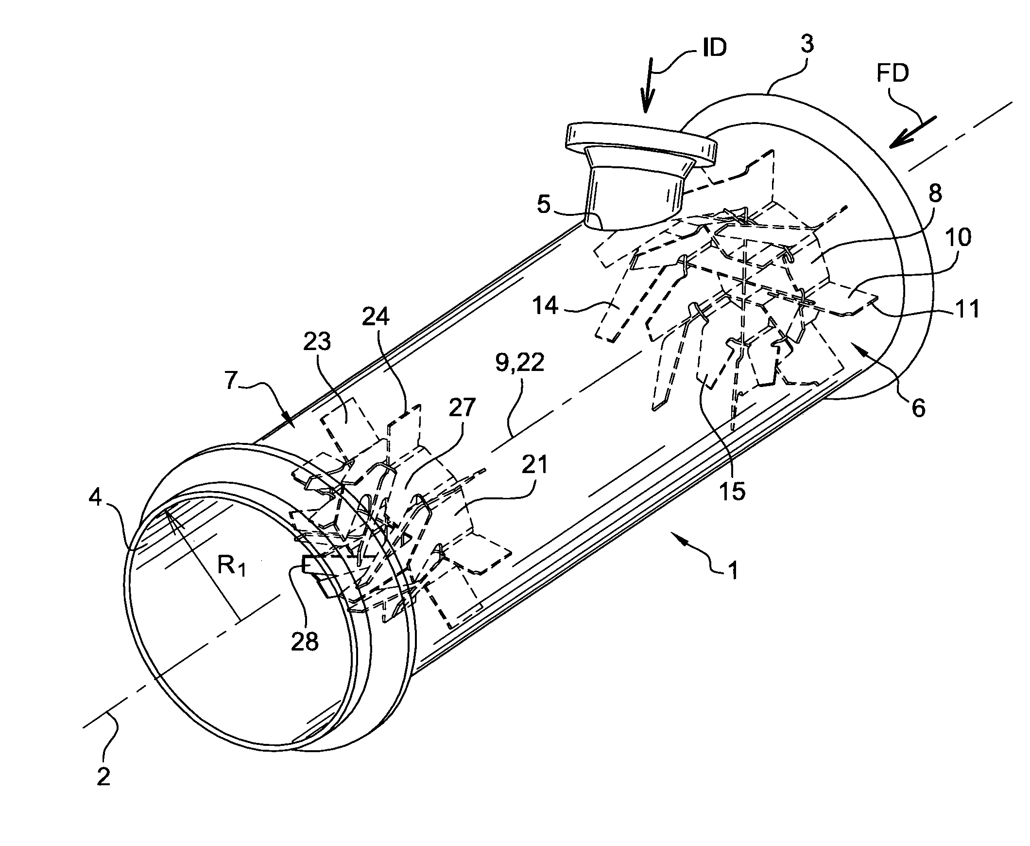
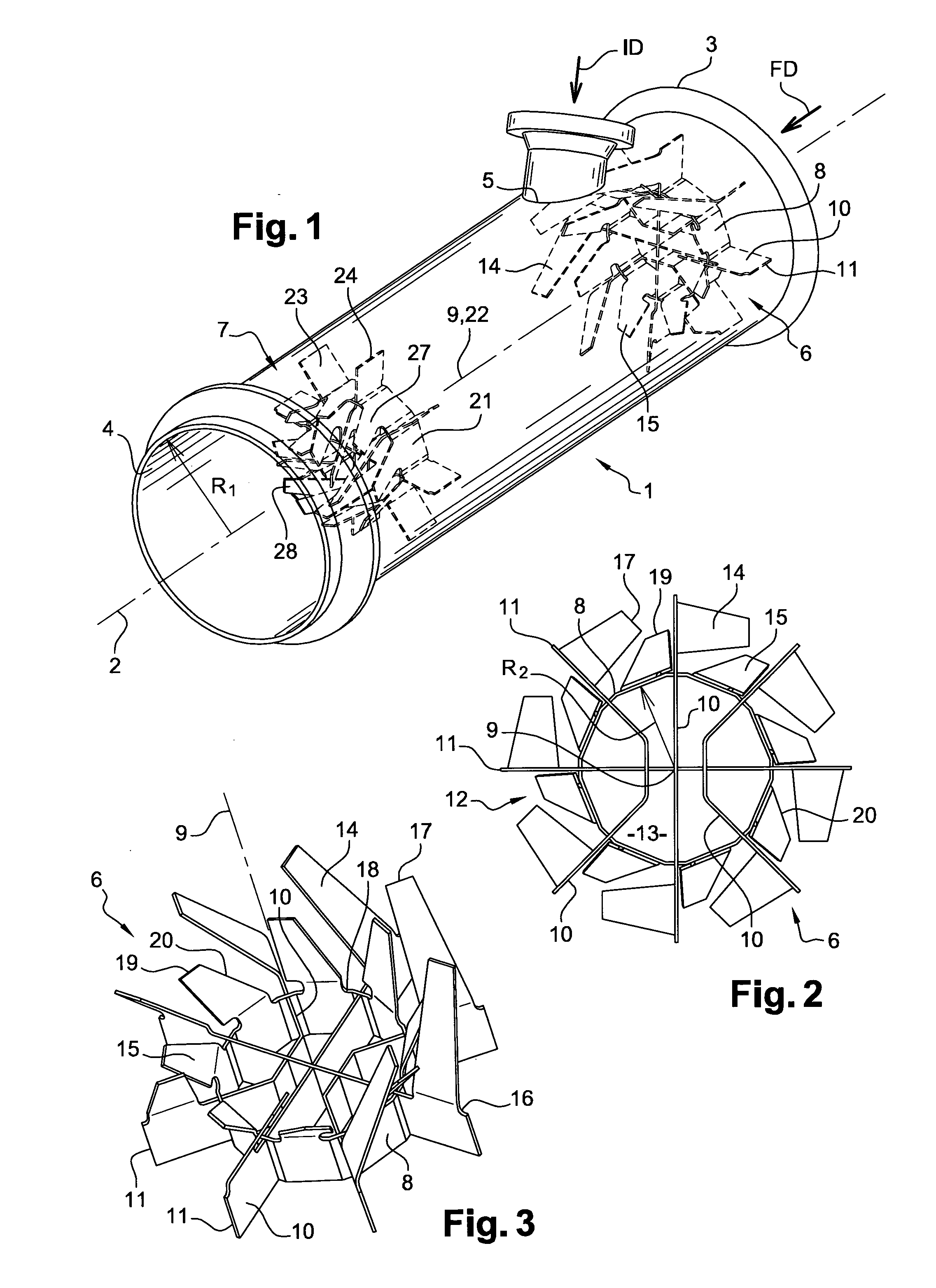
[0045]FIG. 1 shows a pipe 1 which is an exhaust pipe of an engine, typically a diesel engine. Only a straight portion of pipe 1 is illustrated, however pipe 1 can include several bends, upstream and / or downstream from said straight portion. The pipe 1 has a central axis 2 which extends longitudinally in the straight portion. The pipe 1 has a radius R1.

[0046]The engine exhaust gases can flow inside pipe 1 from its inlet 3, on the engine side, towards its outlet 4, where said gases are directed towards a non depicted catalytic converter before being released into the atmosphere. The general flow direction FD of exhaust gases is substantially parallel to the pipe central axis 2 (upstream from any mixing device designed to generate turbulence). The words “upstream” and “downstream” are used with respect to said flow direction FD. The word “inner” refers to a part located closer to the pipe axis 2 as opposed to the word “outer”.

[0047]An injection inlet 5 is provided in the pipe wall. A n...


PUM

PropertyMeasurementUnit
widthaaaaaaaaaa
areaaaaaaaaaaa
wettingaaaaaaaaaa

Abstract

A mixing system includes a pipe having a longitudinal axis, in which exhaust gases can flow in a flow direction, a nozzle designed to inject a fluid inside the pipe from an injection inlet arranged in the pipe wall, according to an injection direction, a first mixing device positioned inside the pipe upstream from the injection inlet, the first mixing device including a peripheral portion including blades capable of creating a peripheral swirl along the pipe wall, and a central portion designed to create substantially no turbulence, and a second mixing device positioned inside the pipe downstream from the injection inlet, the second mixing device including a central portion including blades capable of creating a swirl inside the pipe.

Description

BACKGROUND AND SUMMARY[0001]The present invention relates to a mixing system for an exhaust gases after-treatment arrangement, for example in an exhaust gas pipe. Said system is especially designed to improve the mixing of a fluid with the exhaust gases of a thermal engine, while also preventing the solid deposits of said fluid on the pipe wall. The present invention can be used for example in an exhaust pipe of a diesel engine wherein an aqueous solution of urea is injected in view of an after-treatment of the exhaust gases.[0002]Exhaust gases formed in the combustion of fuel in an internal combustion engine may contain a proportion of undesirable substances such as nitrogen oxides (NOx), carbon monoxide (CO), un-burnt hydrocarbons (HC), soot, etc. . . . .[0003]To reduce air pollution, vehicles are therefore equipped with various after-treatment systems that deal with undesirable substances in exhaust gases.[0004]A common exhaust gases after-treatment system is a so called selectiv...

Claims


Application Information

Patent Timeline
Patent Type & Authority Applications(United States)
IPC IPC(8): F01D5/00
CPCB01F3/04049B01F5/0473F01D5/00F01N3/2892F01N2240/20B01F5/0616B01F23/2132B01F25/3141B01F25/4315
Inventor STASKOWIAK, DANIELLACROIX, FABIENMORETTI, SOLINNE
Owner VOLVO LASTVAGNAR AB
Why Eureka
Try Eureka