Dual-Pressure Dual-Compartment Fluid Tank

a dual-compartment, fluid tank technology, applied in the direction of heating types, domestic hot water supply systems, lighting and heating apparatus, etc., can solve the problems of increasing heat loss, complex and difficult system construction, and the use of separate hydronics and potable water tanks requires substantially more materials, so as to facilitate the transfer of heat energy between compartments and improve the fluid mixing within the compartments

Inactive Publication Date: 2010-07-08
ELECTRO IND
View PDF28 Cites 7 Cited by
  • Summary
  • Abstract
  • Description
  • Claims
  • Application Information

AI Technical Summary

Benefits of technology

[0009]An improved dual-pressure dual-compartment tank for transferring heat energy between isolated solutions is disclosed. The tank has one fluid compartment positioned within a second fluid compartment so that the transfer of heat energy between the compartments is facilitated. One of the compartments is maintained at a substantially higher pressure than the other so that if a divider between the compartments ruptures, the low pressure fluid will not contaminate the high pressure fluid. Additionally, the divider may take a variety of shapes to improve fluid mixing within the compartments by accelerating or decelerating the fluid. Also, the divider may be shaped to provide an amount of surface area between compartments that is inversely proportional to the local temperature gradient between the compartments. These designs may include shapes such as cones, corrugated cylinders, corrugated cones, or cones with outer spirals. The foregoing summary does not limit the invention, which is defined by the claims. Similarly, neither the title nor the abstract is to be taken as limiting in any way the scope of the disclosed invention.

Problems solved by technology

Although hot hydronics fluid and hot potable water are both stored in tanks, hydronics fluid is usually stored separately from potable water systems due to the risk of chemicals, bacteria, or other substances contaminating the potable water supply.
In addition to increasing heat losses, the use of separate hydronics and potable water tanks requires substantially more materials, such as insulation, for construction.
These systems typically employ complex and difficult to construct systems for ensuring that the hydronics solution does not contaminate the potable water supply.
Despite somewhat improved efficiencies of these dual compartment tanks, these systems substantially increase the complexity and cost of tank fabrication.
These previous systems do not provide a tank with a section divider whose construction and design is simplified by using a pressure differential as a containment backup in the event of a tank separator rupture.
Additionally, these previous systems do not sufficiently address the problem of temperature gradient stratification within isolated compartments.

Method used


Image

  • Dual-Pressure Dual-Compartment Fluid Tank
  • Dual-Pressure Dual-Compartment Fluid Tank
  • Dual-Pressure Dual-Compartment Fluid Tank

Examples


Embodiment Construction

[0045]The present invention may be used with any type of fluid heat exchange system and is particularly suited for preventing cross contamination of fluids that are in thermal communication with each other. However, for descriptive purposes, the present invention will be described in use with potable water and hydronics heating systems.

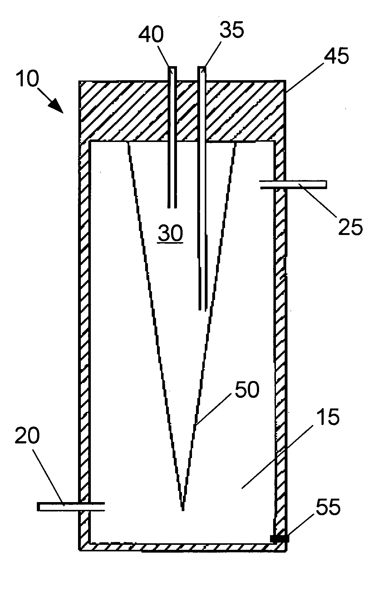
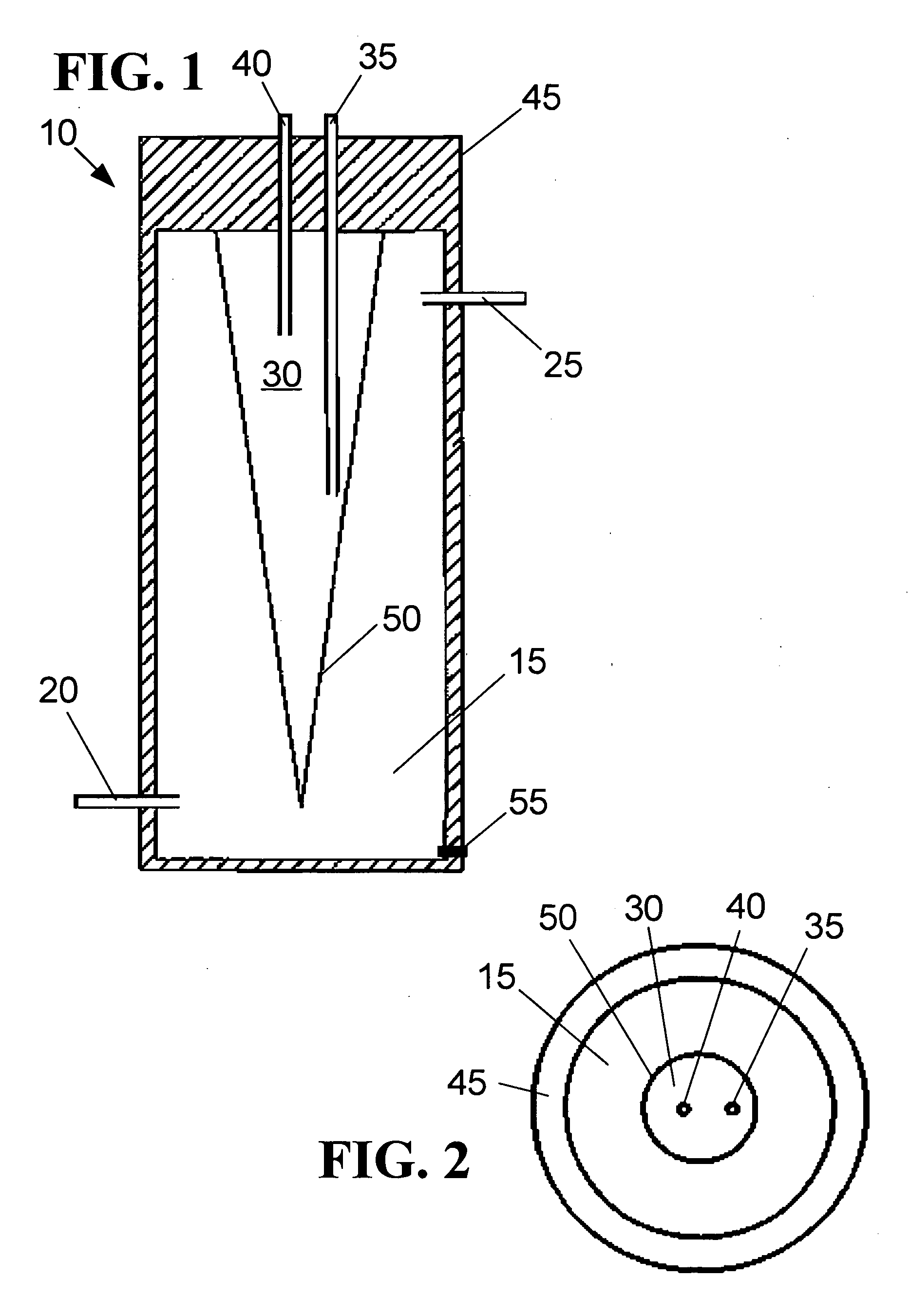
[0046]FIG. 1 shows a side view of a dual compartment hydronics fluid and potable water tank 10. A hydronics compartment 15 or vessel with a hydronics fluid input 20 and a hydronics fluid output 25 may be part of a larger circulation system providing heating to a structure via a plurality of conduits and radiators (not shown). Substantially enclosed within the hydronics compartment 15 is a potable water compartment 30 with a water input 35 and a water output 40. In the embodiment shown in FIG. 1, potable water from a municipal or well source is fed into the water compartment via the water input. Thermal insulation 45 surrounds both of the compartments ...


PUM


Abstract

An improved dual-pressure dual-compartment tank for transferring heat energy between two solutions while physically isolating the solutions from each other is disclosed. The tank has one fluid compartment positioned within a second fluid compartment such that the transfer of heat energy between the compartments is facilitated. One of the compartments is structured to maintain a substantially higher pressure than the other compartment so that if a physical divider between the compartments were to fail, the lower pressure fluid would not contaminate the higher pressure fluid. Additionally, the divider may take a variety of shapes to improve fluid mixing by accelerating or decelerating the fluid, and/or to provide an amount of surface area between compartments that is inversely proportional to the local temperature gradient between the compartments. These designs may include shapes such as a cone, a corrugated cylinder, a corrugated cone, or a cone with an outer spiral for improving mixing, thermal transfer, or to simplify construction of the dual-compartment tank.

Description

FIELD OF THE INVENTION[0001]The present invention relates generally to devices, systems, and methods for providing hot water to a utility use and to a general residential or commercial use. More particularly, the invention relates to devices, systems, and methods in which potable water for human use is heated by placing it in proximity to a hot hydronics solution.BACKGROUND[0002]Conventional potable hot water heaters are usually of the tank-type having an electric, gas or, other heating element at their bottom. A cold water source such as a well or municipal water supply provides water to the tank, and an outlet from the tank is connected to sinks, dishwashers, washing machines, bath tubs, or other devices that use hot water.[0003]Hydronic fluid storage and heating compartments are also generally of the tank-type and may be heated by a variety of fuels including natural gas, oil, coal, resistive electric heating, or high efficiency electrically powered heat pumps. Hydronic heating t...

Claims


Application Information

Patent Timeline
Patent Type & Authority Applications(United States)
IPC IPC(8): F28D15/00B65D25/04
CPCF24D17/0031F24H1/20F24H9/0015F28D1/0213F28D7/106F28F13/12F28D2020/0082F28D2020/0086
Inventor SEEFELDT, WILLIAM J.KRAUSE, JOEL D.
Owner ELECTRO IND
Why Eureka
Try Eureka