Heat conduction systems

a heat conduction system and heat exchange technology, applied in the field of heat conduction systems, can solve the problems of very rapid heat transfer axially along the core and minimal radial heat transfer, and achieve the effect of axial heat transfer

Active Publication Date: 2016-03-29
VON HACK PRESTINARY RICHARD +1
View PDF10 Cites 12 Cited by
  • Summary
  • Abstract
  • Description
  • Claims
  • Application Information

AI Technical Summary

Benefits of technology

[0006]In accordance with a preferred embodiment hereof, this invention provides a novel solid-medium heat conduction system for conducting heat over substantial distances and extracting that heat for useful purposes. The system includes various connectable modules of internally insulated pipe having a core of a solid composition of carbon foam glass and graphene. Graphene is a single-layer of bonded carbon atoms in a hexagonal grid pattern. Heat transfer axially along the core is very rapid, whereas radial heat transfer is minimal, due to the lack of a significant radial thermal gradient as a result of the layer, or layers, of insulation between the pipe and the core.

Problems solved by technology

Heat transfer axially along the core is very rapid, whereas radial heat transfer is minimal, due to the lack of a significant radial thermal gradient as a result of the layer, or layers, of insulation between the pipe and the core.

Method used


Image

  • Heat conduction systems
  • Heat conduction systems
  • Heat conduction systems

Examples


Embodiment Construction

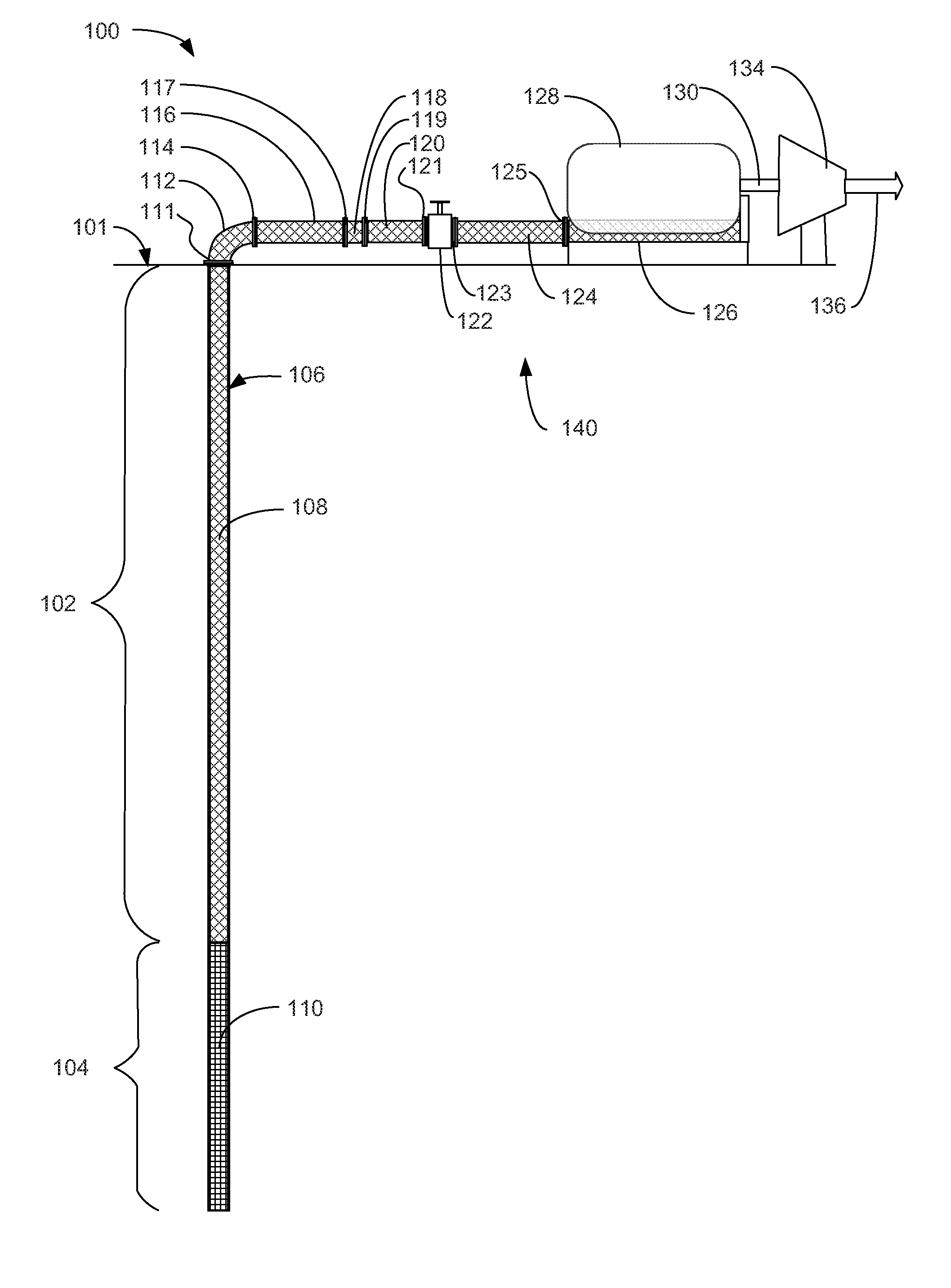
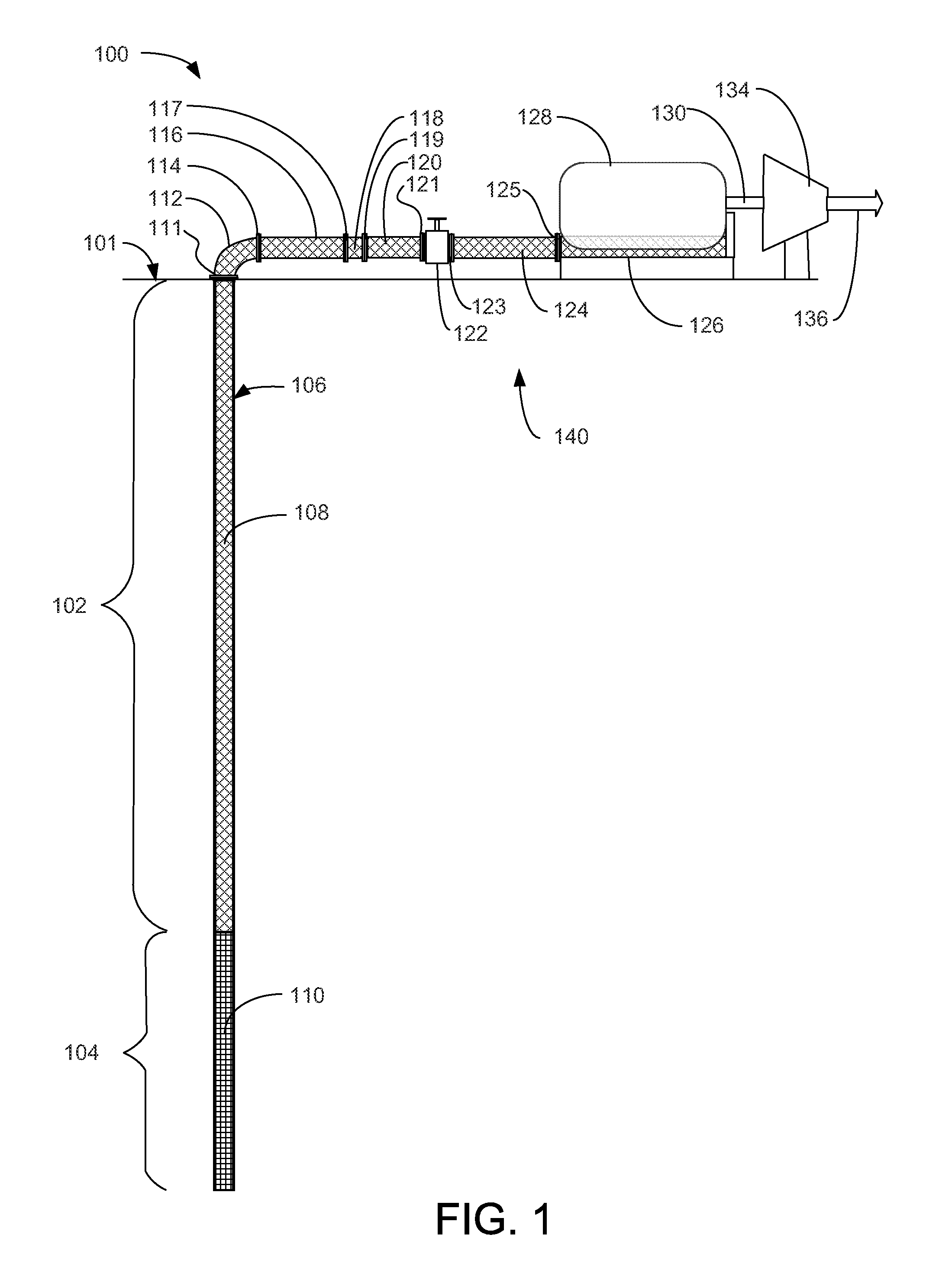
[0038]FIG. 1 is a diagrammatic view of a geothermal application of an exemplary embodiment of the heat conduction system 100, according to a preferred embodiment of the present invention. Heat conduction system 100 is installed in a well pipe 106 below the surface 101 of the Earth. Heat conduction system 100 includes a down-hole heat exchanger portion 110 in geothermally active zone 104, an internally insulated heat conduction portion 108 in geothermally less active zone 102, and a top-side installation 140.

[0039]Exemplary top side installation 140 includes a heat conduction pipe bend module 112, a first heat conduction module 116; a pipe break heat conduction module 118, a second heat conduction module 120, a heat conduction shut-off valve 122, and a third heat conduction module 124. Exemplary top side installation 140 also includes a topside, or output, heat exchanger 126, which is illustrated as a bed of heat-conducting combination of carbon foam glass and graphene abutting a boi...


PUM


Abstract

A heat conduction system including modular pipes housing a solid heat conductor made of a combination of carbon foam glass and grapheme and, for conductors, insulated from the outermost pipe by an insulating layer and with an annular gas purging gap for high-temperature applications. Also included in the system are thermal valves, manifolds, and heat exchangers to route and use the thermal energy. In an exemplary use, a down-hole heat exchanger, thermally coupled to a string of heat conduction modules, brings geothermal heat up from abandoned oil wells to operate a boiler and steam turbine. In another exemplary use, waste heat is conducted out of slag for conversion into useful energy. In yet another exemplary use, waste heat is conducted away from a nuclear reactor.

Description

RELATED APPLICATIONS[0001]This application claims the benefit of U.S. provisional patent application 61 / 544,425 filed Nov. 1, 2011 to the same inventors.FIELD OF THE INVENTION[0002]This invention relates to heat conduction systems. More particularly, it relates to a non-fluid, or solid, heat conduction system. More particularly, it relates to a passive method for transferring heat using a zero-carbon footprint as far as the atmosphere is concerned.BACKGROUND[0003]A problem in extraction of geothermal energy and other isolated energy sources, such as nuclear power plants, has been that a heat-conductive fluid must first be pumped to the heat source, where the fluid is heated, then pumped back to a heat exchanger to be extracted for useful purposes or ejected. The cooled fluid output of the heat exchanger may be reused in some applications, or may be waste in other applications, but requires pumping in either case. The heat losses during pumping from the isolated heat source to the he...

Claims


Application Information

Patent Timeline
Patent Type & Authority Patents(United States)
IPC IPC(8): F24J3/08F28F9/00F28F27/02F28F13/00
CPCF28F9/001F24J3/08F28F27/02F28F2013/008Y02E10/10F03G7/04F28F13/00F28F1/14F28F2013/001F28D21/0001F24T10/10
Inventor VON, HACK-PRESTINARY, RICHARDDONOFRIO, RAYMOND, S.
Owner VON HACK PRESTINARY RICHARD
Why Eureka
Try Eureka