Heat transfer system and method for turbine engine using heat pipes

Active Publication Date: 2010-09-23
GENERAL ELECTRIC CO
View PDF22 Cites 13 Cited by
  • Summary
  • Abstract
  • Description
  • Claims
  • Application Information

AI Technical Summary

Benefits of technology

[0005]The above-mentioned shortcomings in the prior art among others are addressed by the present invention, which provides a heat transfer system that removes waste heat from the engine lubrication oil and transfers that heat to engine components that require heating, for example for anti-icing or de-icing purposes. This heat is transferred using heat pipes which are lightweight, sealed, and passive, requiring no valves or pumps. Furthermore, the heat pipes may use a working fluid which is non-flammable to avoid creating a fire hazard within the engine.

Problems solved by technology

This configuration results in a pressure loss and hence a significant fuel burn penalty.
There are also cost and weight penalties associated with this configuration.
Ice accumulation within the engine and over exposed engine structures may be significant.
The accreted ice may lead to partial blocking of the OGV passages and fan instability.
The accumulated ice can also be suddenly shed, for example through continued operation of the engine, a throttle burst from lower power operation to higher power operation, or vibrations due to either turbulence or asymmetry of ice accretion.
However, all of these methods have various disadvantages.
The increased operating temperature and the bleed systems may decrease engine performance.
Electrical heating requires large quantities of electricity for performing the de-icing operation and may require additional electrical generators, electrical circuits and complex interaction logic with the airplane's computers with the attendant increased cost, weight and performance penalties.

Method used


Image

  • Heat transfer system and method for turbine engine using heat pipes
  • Heat transfer system and method for turbine engine using heat pipes
  • Heat transfer system and method for turbine engine using heat pipes

Examples


Embodiment Construction

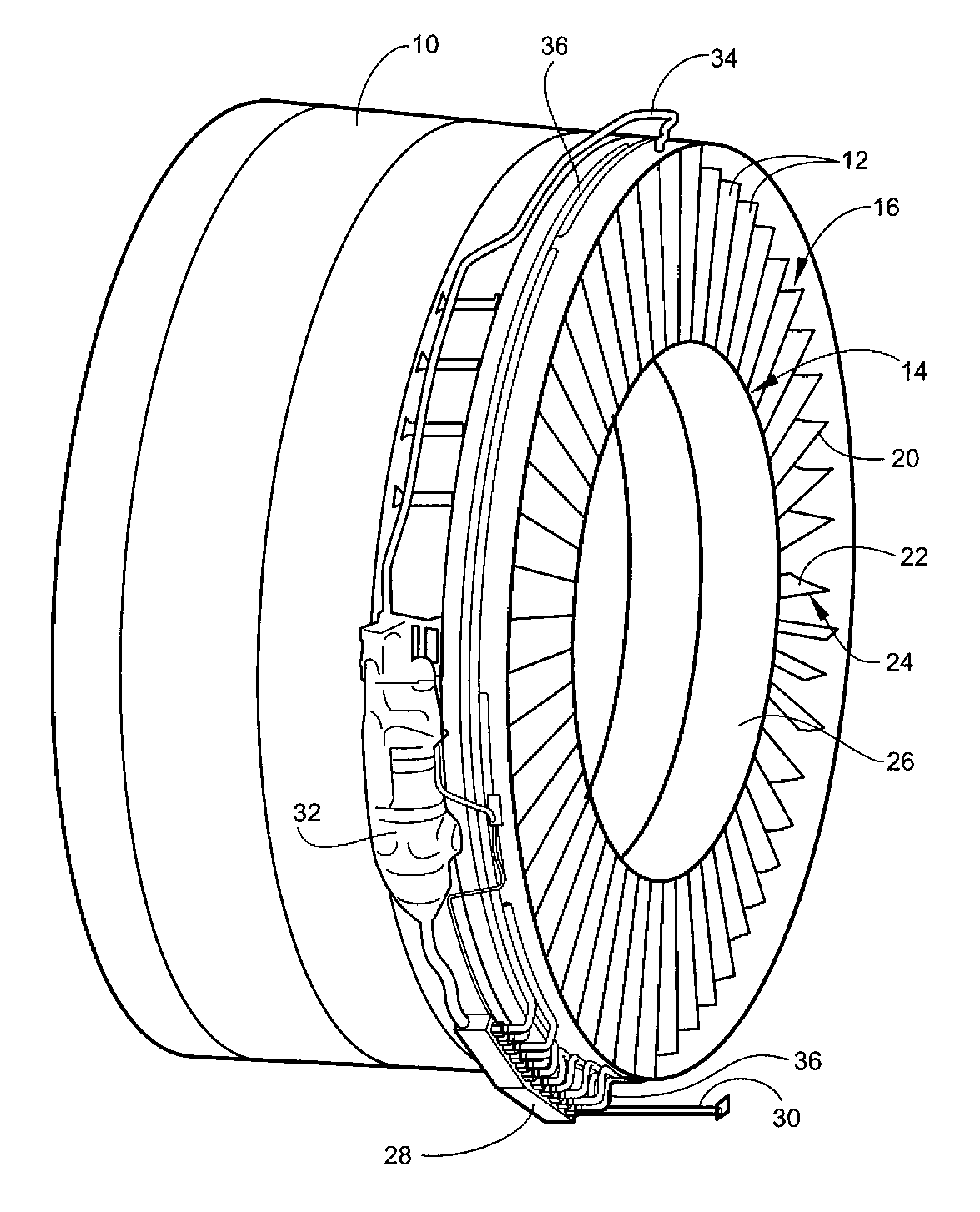
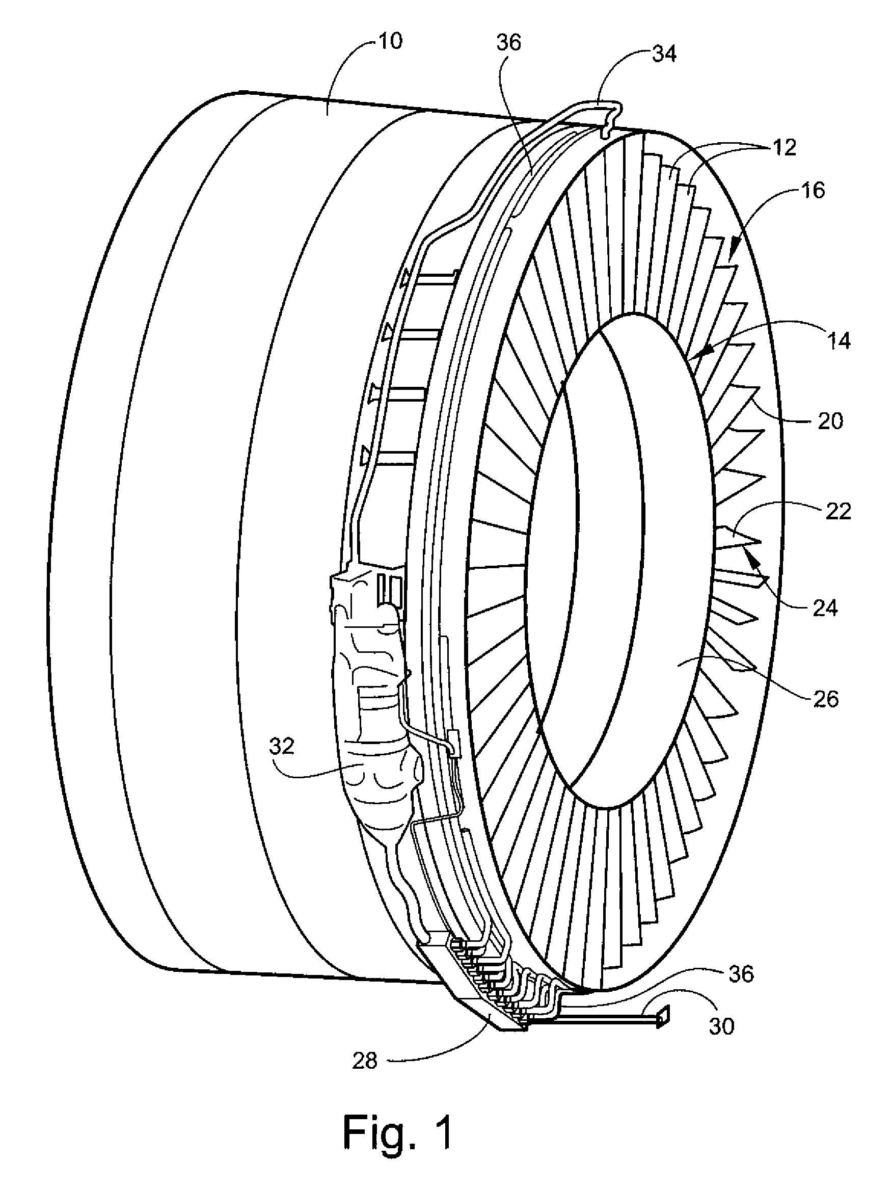
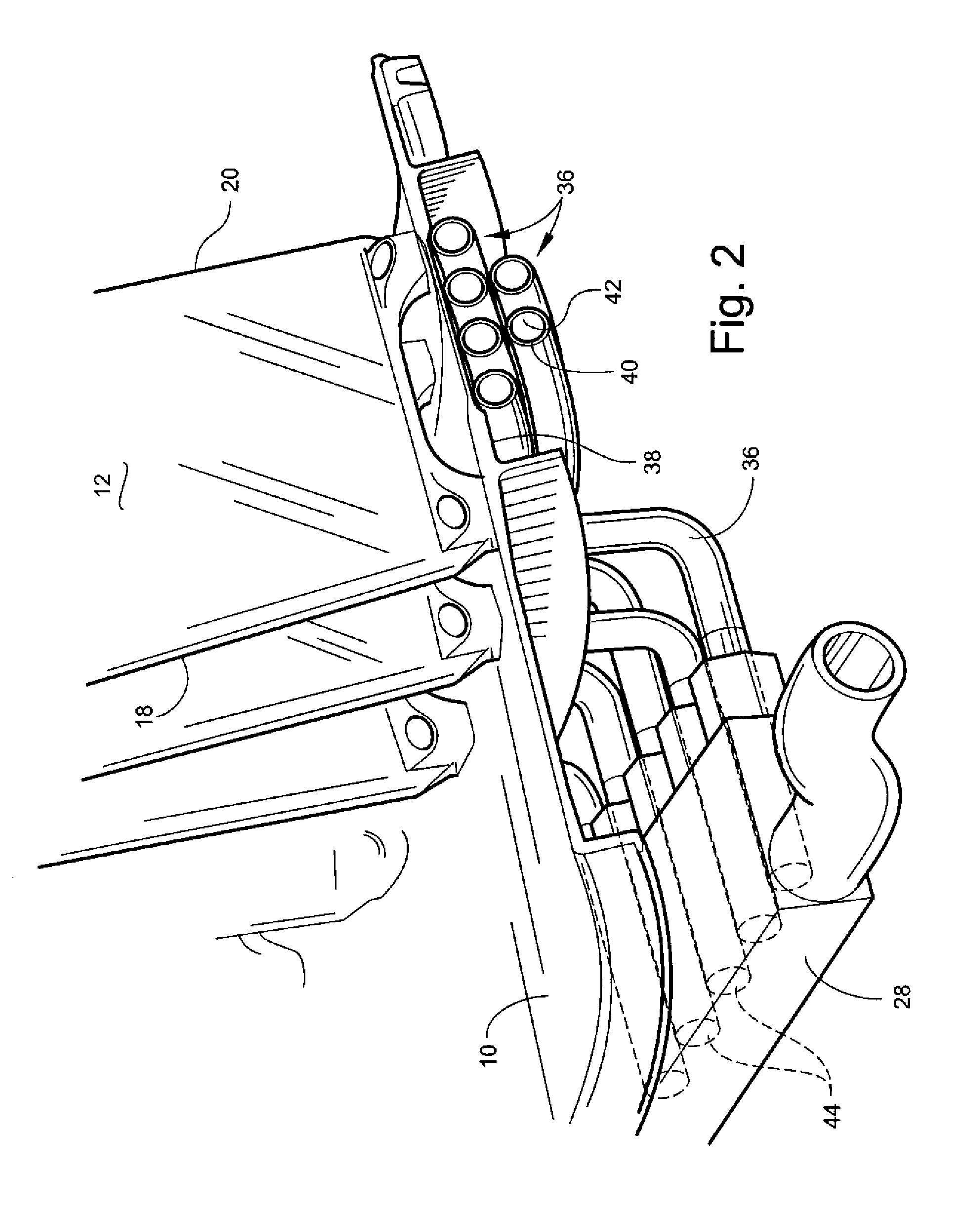
[0014]Referring to the drawings wherein identical reference numerals denote the same elements throughout the various views, FIGS. 1-3 illustrate a portion of a fan module of a gas turbine engine, including an annular fan casing 10. A plurality of outlet guide vanes (OGVs) 12 are connected to and disposed within the fan casing 10. Each of the OGVs 12 (also shown in FIG. 2) has a root 14, a tip 16, a leading edge 18, a trailing edge 20, and opposed sides 22 and 24. The OGVs 12 are airfoil-shaped and are positioned and oriented to remove a tangential swirl component from the air flow exiting an upstream fan (not shown). In the illustrated example, the OGVs also serve as structural members (sometimes referred to as “fan struts”) which connect the fan casing to an inner housing 26. However, in other engine configurations, these functions may be served by separate components. The heat transfer system described herein is equally applicable to OGVs, fan struts, and all other types of genera...


PUM

PropertyMeasurementUnit
Temperatureaaaaaaaaaa
Flow rateaaaaaaaaaa
Electrical conductoraaaaaaaaaa

Abstract

A heat transfer system is provided for a turbine engine of the type including an annular casing with an array of thermally conductive, generally radially-extending strut members disposed therein. The heat transfer system includes at least one arcuate heat pipe disposed in contact with an outer surface of the casing within fore-and-aft limits of the axial extent of the strut members. The heat pipe is thermally coupled to a heat source, such that heat from the heat source can be transferred through the heat pipe and the casing to the strut members.

Description

BACKGROUND OF THE INVENTION[0001]This invention relates generally to turbine engines, and more particularly to a system and method using heat pipes for transferring heat within a gas turbine engine.[0002]Gas turbine engines use pressurized oil to lubricate and cool various components (e.g. bearings, etc.). The oil picks up significant heat in the process which must be rejected to maintain the oil temperature within acceptable limits. Prior art gas turbine engines often employ heat exchangers to cool the engine oil using a relatively cool air stream such as fan discharge air. In turbofan engines, this heat exchanger is often located in the fan duct flow path. This configuration results in a pressure loss and hence a significant fuel burn penalty. It has been estimated that the specific fuel consumption (SFC) penalty associated with this type of configuration can be as high as 1%. There are also cost and weight penalties associated with this configuration.[0003]In addition, in some en...

Claims


Application Information

Patent Timeline
IPC IPC(8): F02K99/00
CPCF01D9/06F01D25/08F01D25/125F02C7/047F02K3/06Y02T50/671Y02T50/675F05D2260/208F05D2300/11F05D2300/133F05C2201/0466F05D2260/207Y02T50/60
Inventor VENKATARAMANI, KATTALAICHERI SRINIVASANMONIZ, THOMAS ORYSTEPHENSON, JUSTIN P.
Owner GENERAL ELECTRIC CO
Why Eureka
Try Eureka