Omnidirectional fan-heatsinks

a fan heatsink and omnidirectional technology, applied in the direction of machines/engines, liquid fuel engines, lighting and heating apparatus, etc., can solve the problems of increasing power consumption of computers, especially the power consumption of central processing units (cpus) used in them, and not achieving high efficiency

Inactive Publication Date: 2004-07-08
LENOVO (SINGAPORE) PTE LTD
View PDF9 Cites 13 Cited by
  • Summary
  • Abstract
  • Description
  • Claims
  • Application Information

AI Technical Summary

Problems solved by technology

The power consumption of computers, especially the power consumption of the central processing units (CPU)s used in them is increasing.
There has been some effort in the art using...

Method used


Image

  • Omnidirectional fan-heatsinks
  • Omnidirectional fan-heatsinks

Examples


Embodiment Construction

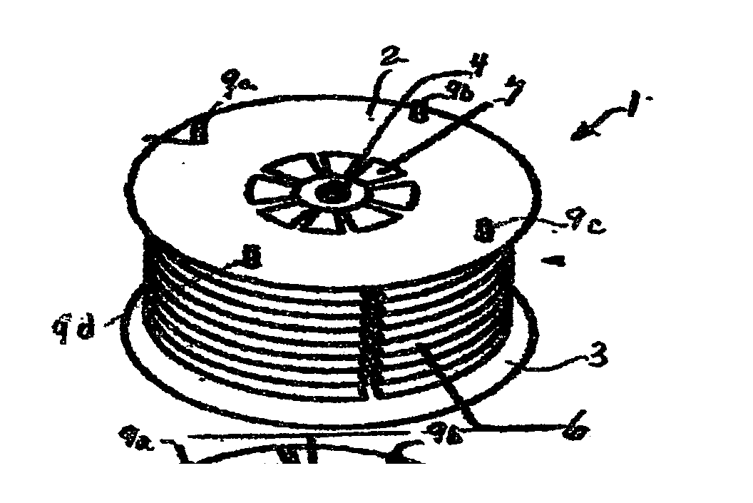
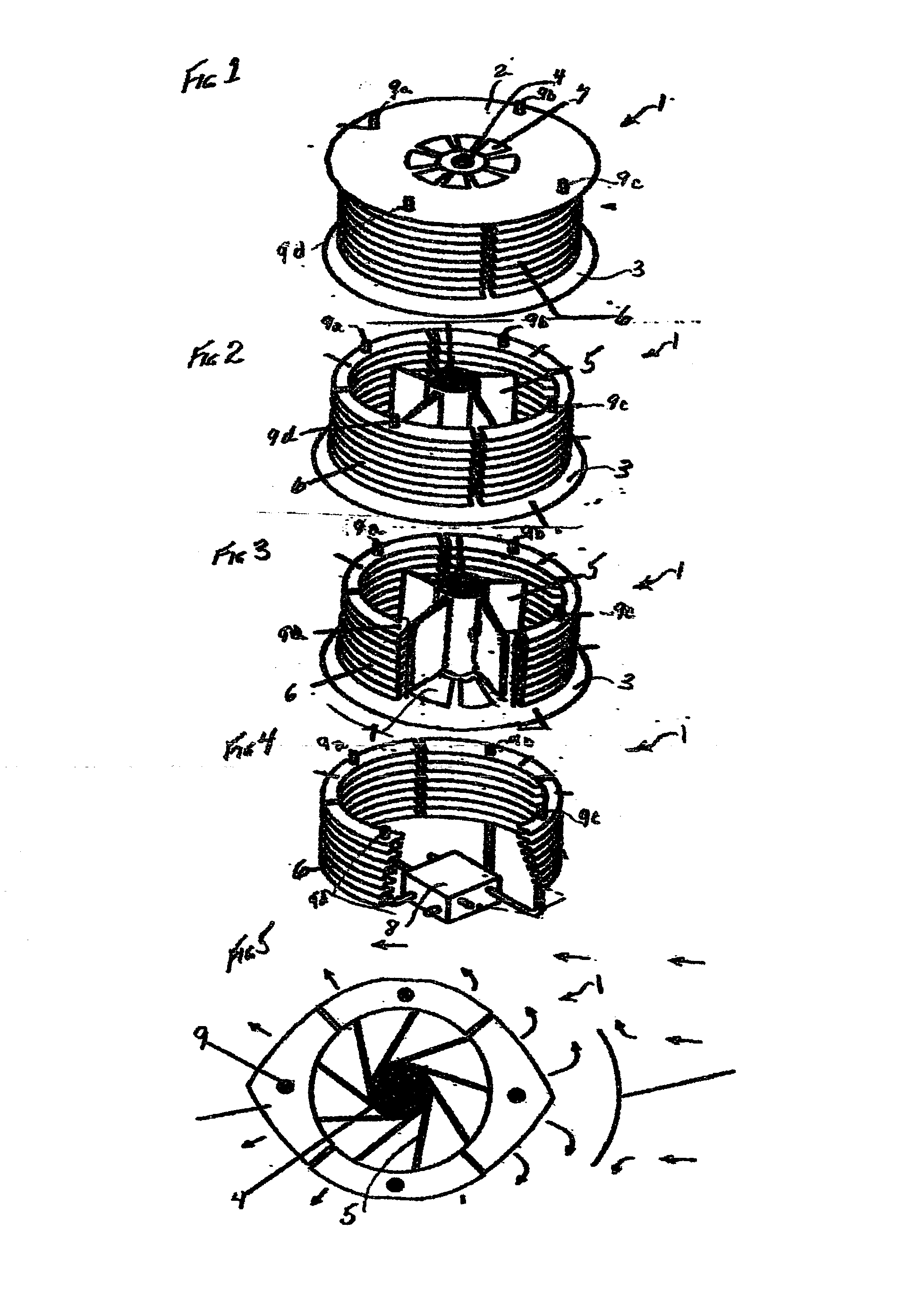
[0011] Referring to FIGS. 1-4 together since all elements are not equally visible in each Figure and wherein like reference numerals are used where appropriate; in accordance with the invention the structural principle of the fan-heatsink 1 may be viewed as consisting of top 2 and bottom 3 cover members with a central power shaft 4 through them, the shaft 4 has fins 5 visible in FIGS. 2 and 3 attached so as to rotate around the shaft between the covers 2 and 3 within a housing of louvered heat exchangers 6 to move an ambient heat bearing gas such as air. The ambient enters the fan-heatsink 1 via inlets 7 through the covers 2 and 3 near the central power shaft 4 and is forced out through the louvers 6 that make up the periphery of the fan-heatsink housing. A heat pipe transfer capability is provided involving a conduction block 8 through which heat pipe conductors 9 (a-d) of which four are shown transfer heat between the conduction block 8 and the louvers 6.

[0012] It will be apparent...


PUM


Abstract

The invention provides a structural principle wherein a combination fan-heatsink type cooling device transfers a large amount of heat into an ambient while producing minimal acoustic noise. The fan-heatsink has top and bottom cover members with a central power shaft between them, the shaft has fins that rotate around the shaft between the covers to move ambient. The ambient enters the fan-heatsink through inlets through the covers near the central power shaft and is forced out through louvers that make up the peripheral of the fan-heatsink housing. The fan-heatsink cooling device is positioned so that heat radiating from the heat source such as a chip enters the housing through the inlets near the central shaft and heat pipes are arranged to carry heat from the chip source to and through the louvers so that the ambient forced through the louvers absorbs heat transferred to the louvers at the place where it is immediately carried out of the fan-heatsink structure.

Description

[0001] The invention is in the field of heat transfer and cooling of electrical apparatus such as semiconductor chips used in the computer and telecommunication types of equipment, and in particular to the solving of heat dissipation problems in devices such as computers where size, weight, and power consumption are constrained.BACKGROUND AND RELATION TO THE PRIOR ART[0002] The power consumption of computers, especially the power consumption of the central processing units (CPU)s used in them is increasing. As examples, the total power of a laptop computer in a few years has increased from about 10 watts to now around 50 watts, and that of a desktop computer has increased form 300 watts to about 500 watts. The CPU portion of the overall power has increased from about 2 to about 18 watts and is expected in the future to approach 40 watts in laptop computers and 30 to 150 watts in desktop computers. Most of the CPU power will have to be dissipated and the efficiency of the dissipation...

Claims


Application Information

Patent Timeline
IPC IPC(8): F04D29/58F28D15/02F28F1/32H01L23/467
CPCF04D29/582F28D15/0275F28F1/32H01L23/467H01L2924/0002H01L2924/00
Inventor MOK, LAWRENCE SHUNGWEI
Owner LENOVO (SINGAPORE) PTE LTD
Why Eureka
Try Eureka