
Spacer For Filled Cell Electrodialysis

Active Publication Date: 2007-06-21
IONICS INC
View PDF5 Cites 5 Cited by
  • Summary
  • Abstract
  • Description
  • Claims
  • Application Information

AI Technical Summary

Benefits of technology

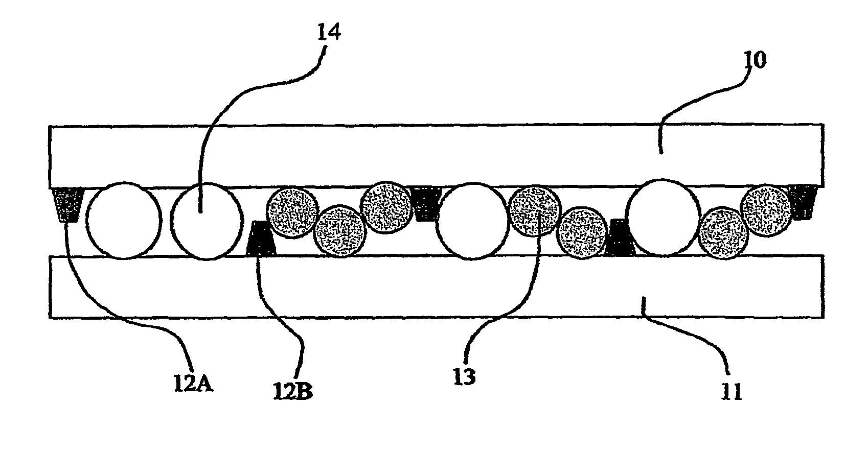
[0008] The present invention provides an improved spacer for an electrodialysis apparatus which has been found to be particularly useful in the filled cells of a filled cell electrodialysis (e.g., electrodeionization or EDI) apparatus. The spacer includes a screen, that, in one aspect provides support to maintain a minimum spacing between the successive membranes bounding the cells of the device. In another aspect, the screen operates as a structural element enhancing the mechanical strength and integrity of the spacer perimeter wall. Screen strands provide distributed tensile cross members mechanically reinforcing the spacer to resist bowing or blowout at elevated operating pressure or temperature. In another aspect, the screen is constituted by fibers or strands, which may be sized and / or positioned to enhance fluid mixing at interfaces between membranes and spacer side walls, reducing or eliminating undesirable short circuiting effects of liquid flowing faster along the intersection of functional packing with spacer walls. Fiber cross section may be further shaped to minimize bead-trapping or orphan bead isolation (e.g., trapping of isolated anion exchange beads adjacent the cation exchange membrane, or cation exchange beads against the anion exchange membrane, thereby limiting or impeding ion transport). Mixing effected by screen strands in such filled cells in accordance with this invention has been found to enhance performance and improve product quality. Additionally, it has been found that screen strands provide mixing of fluid flow at intersections of packing material, membrane surfaces and spacer side walls. Screens in accordance with the present invention allow fluid flow paths to be designed over a wide range of geometries to accommodate a wide range of needs.
[0009] As applied to an EDI apparatus having a packing of exchange beads, screens of the invention may be used in conjunction with a very thin or sparse filling of such beads to provide high hydraulic permeability and to avoid excessive pressure drops for the liquid to be treated. For such design, a screen may be thinner than the largest or nominal bead diameter and have at least one strand layer thinner than the diameter of the smaller particles of the packing. This construction holds the beads in place and may substantially eliminate the need for a larger, structural particle retainer assembly for the active particulates or packing between the membranes.

Problems solved by technology

When long rectilinear flow compartments are employed, the flow distribution in the sub-compartments or flow channels defined by such supported spans of membrane may be subject to edge effects at interfaces between membrane and spacer side walls, creating regions of low or dead flow, and also causing channeling or bypassing by the liquid flow, all of which can result in less than optimal fluid treatment or sub-optimal stack performance.
The proper filling of a dilute cell with a suitable quantity of an appropriate mixture of ion exchange beads to maintain stable membrane spacing and support, assure conductive contact of the resin, and provide an appropriately low flow impedance is not a straightforward task but rather one that may involve considerable experimentation.
Some researchers have proposed, for example, that the spacer frame elements, or even the screen / mesh itself be formed of ion exchange material, that a cell filling include ion-exchange felt or textile, or that the ion exchange membranes incorporate ion exchange fibrils that project from the membrane surface into a fluid flow path, but various cost and practical construction factors have limited commercial implementation of such proposals.
Thus, whatever specific constructions may be employed, the provision of thin, resin-holding flow cells defined between many sets of parallel ion exchange membranes that are separated by spacer frames, poses a complex problem of hydraulics, chemical engineering and structural design.

Method used


Image

  • Spacer For Filled Cell Electrodialysis
  • Spacer For Filled Cell Electrodialysis
  • Spacer For Filled Cell Electrodialysis

Examples


Embodiment Construction

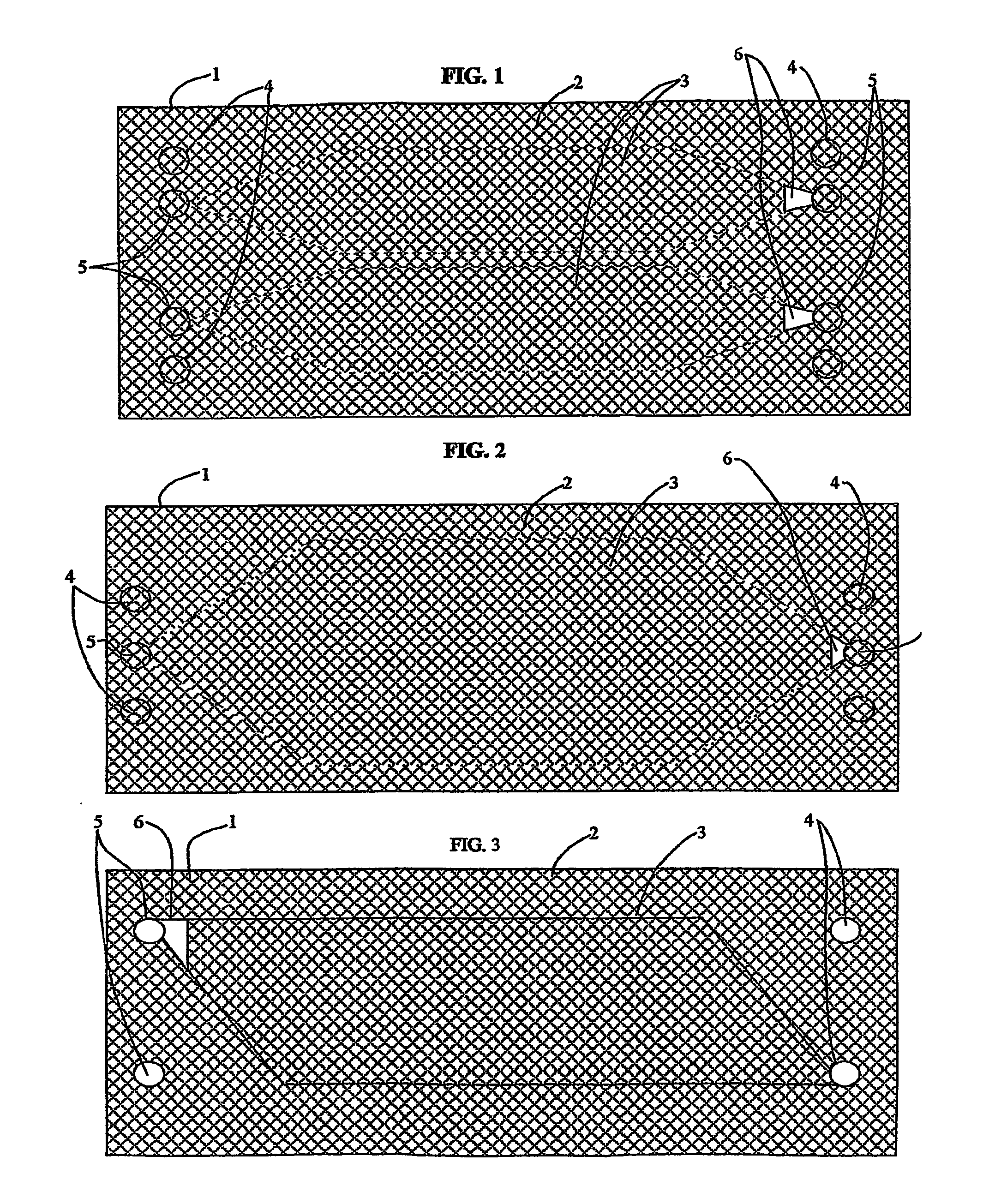
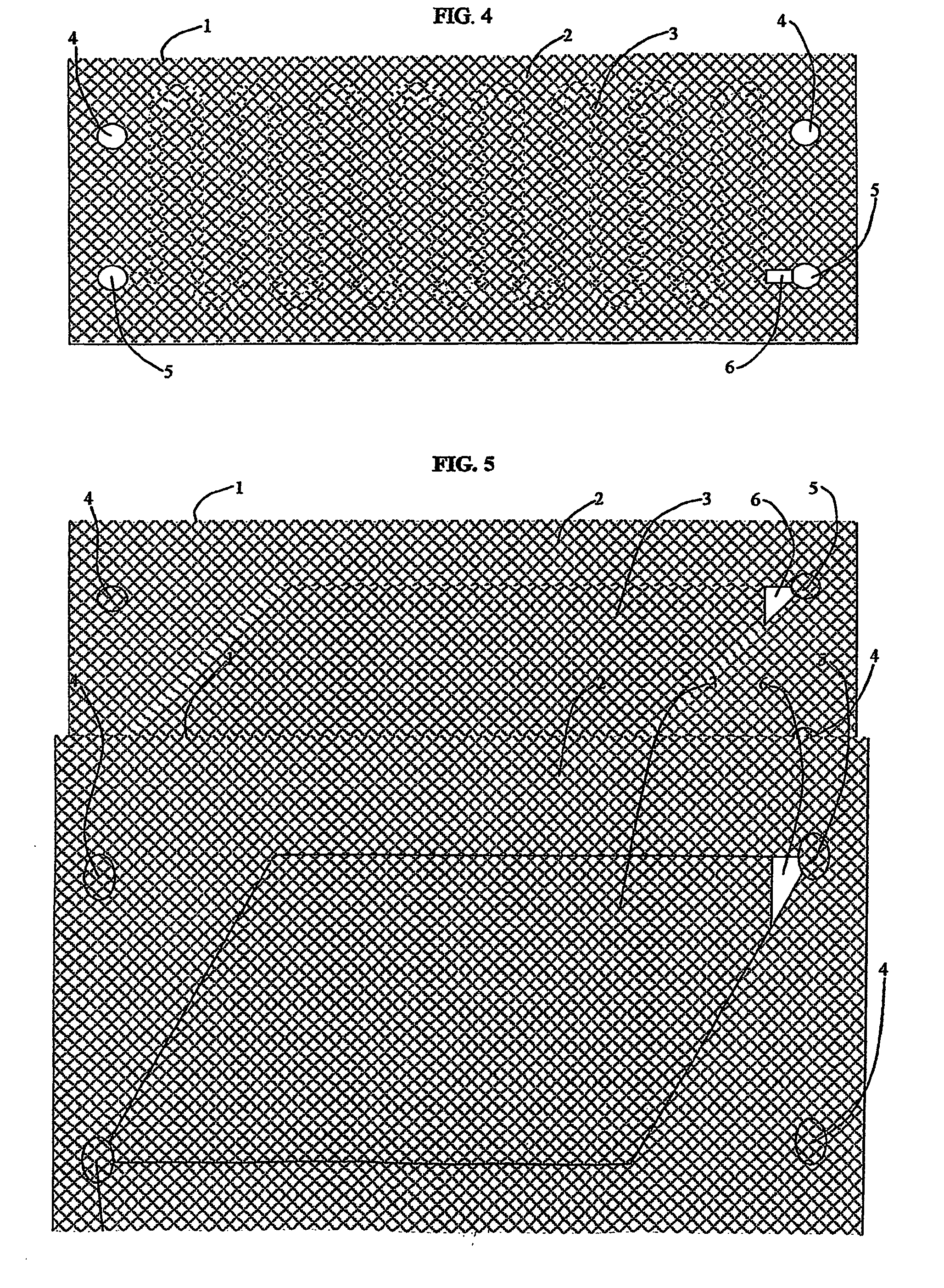
[0023]FIGS. 1 through 6 show diagrammatic plan views of different screen spacer designs in accordance with the present invention to illustrate a range of possible flow cell geometries and construction details. The screen spacers, all denoted by reference numeral 1 for purposes of illustration, are all intended for a rectangular, frame-type EDI stack, and thus have a thin, flat, generally rectangular and planar aspect, for which details of possible flow channels, ports and shape will be discussed. However, one of ordinary skill in this art will understand and appreciate that the various illustrated embodiments of the invention may be applied, with suitable modifications, to other known EDI device architectures, including EDI devices formed as a cylindrical stack of flat disk-shaped cells, and devices having spiral-wound cells in an overall cylindrical shape; and, each of these alternative EDI device architectures embodying a screen element in accordance with this invention is conside...


PUM

PropertyMeasurementUnit
Thicknessaaaaaaaaaa
Pressureaaaaaaaaaa
Angleaaaaaaaaaa

Abstract

A spacer element (1) is disclosed having an integral screen for use in filled cell electrodialysis. The spacer (1) has a continuous portion (2) impermeable to flow and a screen (3) which spans a centrally-located flow treatment region that contains active treatment material, such as ion exchange beads. The screen (3) may perform a structural function, allowing operation at elevated pressure, and may also define a minimum gap between adjacent membranes and enhance mixing along the flow path and at cell boundaries. The spacer element (1) may be configured to enhance hydraulic filling of the cells, and cell architecture is readily implemented in a wide range of useful flow path geometries utilizing the screen spacer element (1).

Description

[0001] The present invention relates generally to improved spacer elements for use in an electrodialysis device, such as in filled cell electrodialysis. A spacer element in accordance with this invention includes a mesh or screen positioned in a liquid flow path between membrane elements or alongside a membrane element within a cell. The mesh or screen provides controlled membrane spacing as well as enhanced mixing along boundaries of the flow region within the cell, and constitutes a cross lattice or structural reinforcement against bowing under pressure. A functional packing, such as ion exchange or other active material, is retained in the cell. Different embodiments of the present invention provide cells with a wide range of flow path geometries to accommodate different system uses and specifications. BACKGROUND AND FIELD OF THE INVENTION [0002] The invention pertains to filled spacers for filled cell electrodialysis apparatus, commonly called EDI or electrodeionization apparatu...

Claims


Application Information

Patent Timeline
IPC IPC(8): C25B13/00B01D61/48B01D61/50B01J47/08C02F1/46C02F1/469
CPCB01D61/48B01D61/50B01D69/06B01D2313/08B01D2325/06B01J47/08C02F1/4604C02F1/469C02F2201/46115B01D69/10
Inventor CARSON, WILLIAMW
Owner IONICS INC
Learn More