Methods and apparatus for optical propagation improvement system

a technology of optical propagation and optical propagation, applied in the field of aircraft sensor systems, can solve the problems of known failures or limited results, and achieve the effects of facilitating airflow directing, facilitating regularizing concomitant aero-optic aberrations, and facilitating airflow directing

Inactive Publication Date: 2009-10-01
INNOVATIVE TECH APPL COMPANY +1
View PDF19 Cites 11 Cited by
  • Summary
  • Abstract
  • Description
  • Claims
  • Application Information

AI Technical Summary

Benefits of technology

[0010]In another aspect, an optical propagation improvement system coupled to a directed energy device is provided. The directed energy device is configured to generate and transmit a directed energy beam. The optical propagation improvement system includes at least one air speed sensor and at least one of at least one air pressure transducer and at least one optical aberration sensor. The system also includes a computer processor coupled with the at least one air speed sensor and the at least one of at least one air pressure transducer and at least one optical aberration sensor. The computer processor is configured to determine effects of a separated turbulent shear layer on the directed energy beam including distortions to a phase of the energy beam's wavefront. The computer processor is also configured to determine an adjusted phase of the directed energy beam prior to transmission through the separated turbulent shear layer based on the determined effects such that the energy beam's wavefront is optimized after transmission through the separated turbulent shear layer. The directed energy system includes an adaptive optic device that is configured to generate and transmit the directed energy beam. The adaptive optic device is coupled to the computer processor and the computer processor is configured to adjust the phase of the energy beam's wavefront prior to transmission through the separated turbulent shear layer such that the energy beam's wavefront is optimized after transmission through the separated turbulent shear layer. The at least one air pressure transducer includes a plurality of air pressure transducers. The at least one optical aberration sensor includes a plurality of optical aberration sensors. Each of the plurality of air pressure transducers and optical aberration sensors is positioned within a cavity defined within a portion of an aircraft. At least one of the plurality of air pressure transducers and optical aberration sensors is positioned within a forward portion of the cavity and at least one of the plurality of air pressure transducers and optical aberration sensors is positioned within an aft portion of the cavity. The system further includes a rigid material cover that extends radially outward a first distance from an aircraft fuselage. A turret section of the directed energy system extends radially outward a second distance from the aircraft fuselage. The first distance is greater than the second distance and a difference between the first distance and the second distance facilitates directing of airflow to generate aeroacoustic resonances that facilitate regularizing concomitant aero-optic aberrations based on a predetermined range of air speed. The aeroacoustic resonances are at least partially manifested as quasi-periodic air pressure oscillations within the cavity that stimulate coherent motions of a separated turbulent shear layer that spans the cavity. The at least one air pressure transducer is configured to generate and transmit an air pressure signal that is substantially representative of air pressure in the vicinity of the air pressure transducer. The at least one optical aberration sensor is configured to generate and transmit an aberrated wavefront signal that is substantially representative of wavefronts in the vicinity of the optical aberration sensor. The at least one air speed sensor is configured to generate and transmit an air speed signal that is substantially representative of air speed in the vicinity of the directed energy device. The computer processor is programmed with aeroacoustic resonance data that includes aeroacoustic resonance frequency and aeroacoustic resonance amplitude values as a function of at least one of aircraft speed signals and cavity air pressure signals and wavefront aberration signals. The computer processor is programmed to determine a real time frequency and amplitude of an associated aeroacoustic resonance as a function of aircraft speed signals and cavity air pressure signals.
[0011]In a further aspect, an aircraft is provided. The aircraft includes an aircraft fuselage and a turret section coupled to the aircraft fuselage. The aircraft also includes a directed energy device at least partially enclosed within the turret section. The directed energy device is configured to generate and transmit a directed energy beam. The aircraft further includes an optical propagation improvement system coupled to the directed energy device. The optical propagation improvement system includes at least one air speed sensor and at least one of at least one air pressure transducer and at least one optical aberration sensor. The system also includes a computer processor coupled with the at least one air speed sensor and the at least one of at least one air pressure transducer and at least one optical aberration sensor. The computer processor is configured to determine effects of a separated turbulent shear layer on the directed energy beam including distortions to a phase of the energy beam's wavefront. The computer processor is also configured to determine an adjusted phase of the directed energy beam prior to transmission through the separated turbulent shear layer based on the determined effects such that the energy beam's wavefront is optimized after transmission through the separated turbulent shear layer. The directed energy system includes an adaptive optic device that is configured to generate and transmit the directed energy beam. The adaptive optic device is coupled to the computer processor and the computer processor is configured to adjust the phase of the energy beam's wavefront prior to transmission through the separated turbulent shear layer such that the energy beam's wavefront is optimized after transmission through the separated turbulent shear layer. The at least one air pressure transducer includes a plurality of air pressure transducers. The at least one optical aberration sensor includes a plurality of optical aberration sensors. Each of the plurality of air pressure transducers and optical aberration sensors is positioned within a cavity defined within a portion of the aircraft. At least one of the plurality of air pressure transducers and optical aberration sensors is positioned within a forward portion of the cavity and at least one of the plurality of air pressure transducers and optical aberration sensors is positioned within an aft portion of the cavity. The system further includes a rigid material cover that extends radially outward a first distance from the aircraft fuselage. A turret section of the directed energy system extends radially outward a second distance from the aircraft fuselage. The first distance is greater than the second distance and a difference between the first distance and the second distance facilitates directing of airflow to generate aeroacoustic resonances that facilitate regularizing concomitant aero-optic aberrations based on a predetermined range of air speed. The aeroacoustic resonances are at least partially manifested as quasi-periodic air pressure oscillations within the cavity that stimulate coherent motions of a separated turbulent shear layer that spans the cavity. The at least one air pressure transducer is configured to generate and transmit an air pressure signal that is substantially representative of air pressure in the vicinity of the air pressure transducer. The at least one optical aberration sensor is configured to generate and transmit an aberrated wavefront signal that is substantially representative of wavefronts in the vicinity of the optical aberration sensor. The at least one air speed sensor is configured to generate and transmit an air speed signal that is substantially representative of air speed in the vicinity of the directed energy device. The computer processor is programmed with aeroacoustic resonance data that includes aeroacoustic resonance frequency and aeroacoustic resonance amplitude values as a function of at least one of aircraft speed signals and cavity air pressure signals and wavefront aberration signals. The computer processor is programmed to determine a real time frequency and amplitude of an associated aeroacoustic resonance as a function of aircraft speed signals and cavity air pressure signals.

Problems solved by technology

However, these known attempts have failed or have produced limited results because of the aero-optic aberrations or disturbances arising from density variations in the air flowing over the aircraft, especially in those cases where the directed energy system is pointed in the aft direction of the aircraft.
In both of these cases, where the energy beam is directed forwardly and / or rearwardly, results have been very poor due to a degradation of the energy beam.

Method used


Image

  • Methods and apparatus for optical propagation improvement system
  • Methods and apparatus for optical propagation improvement system
  • Methods and apparatus for optical propagation improvement system

Examples


Embodiment Construction

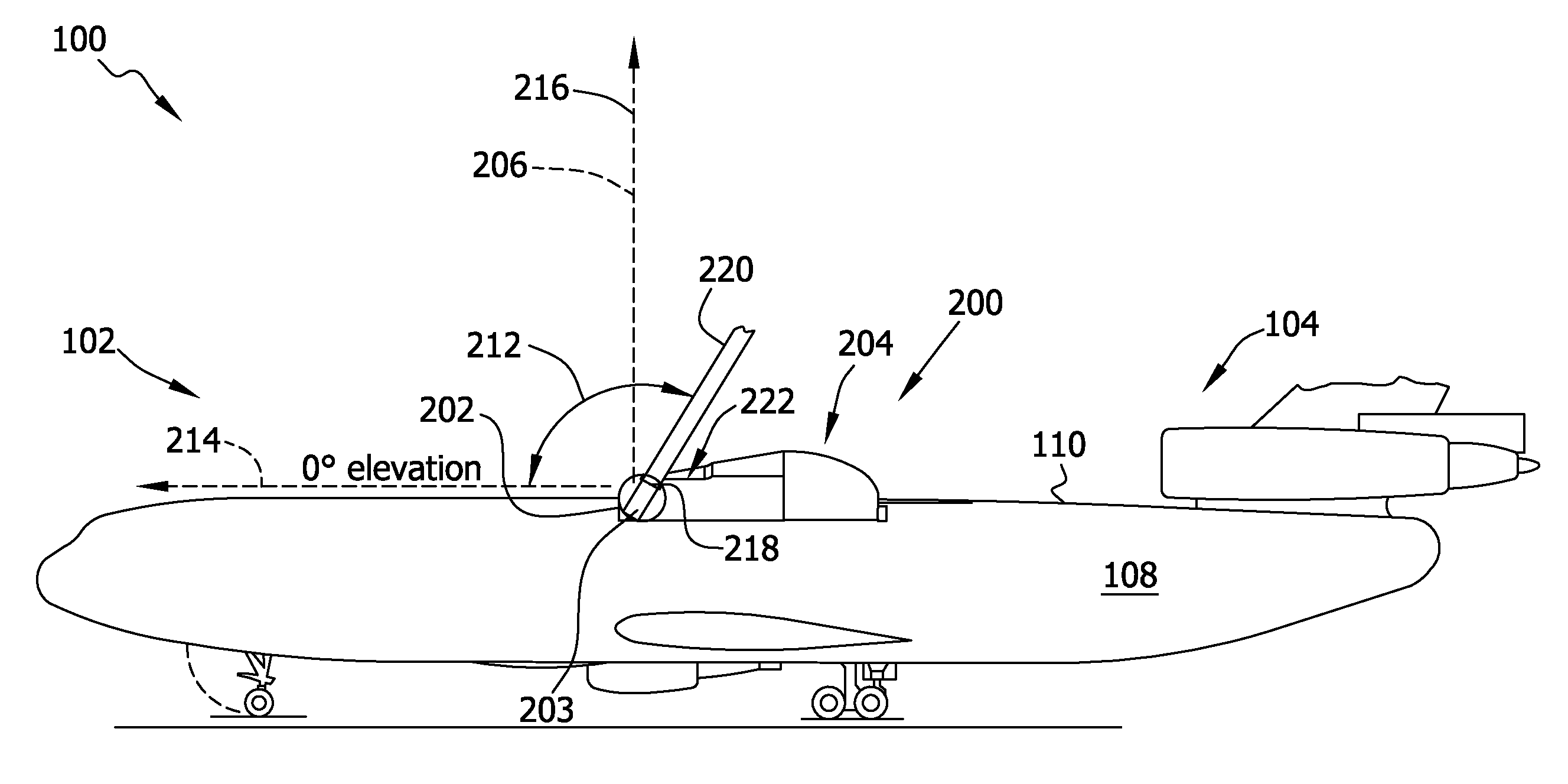
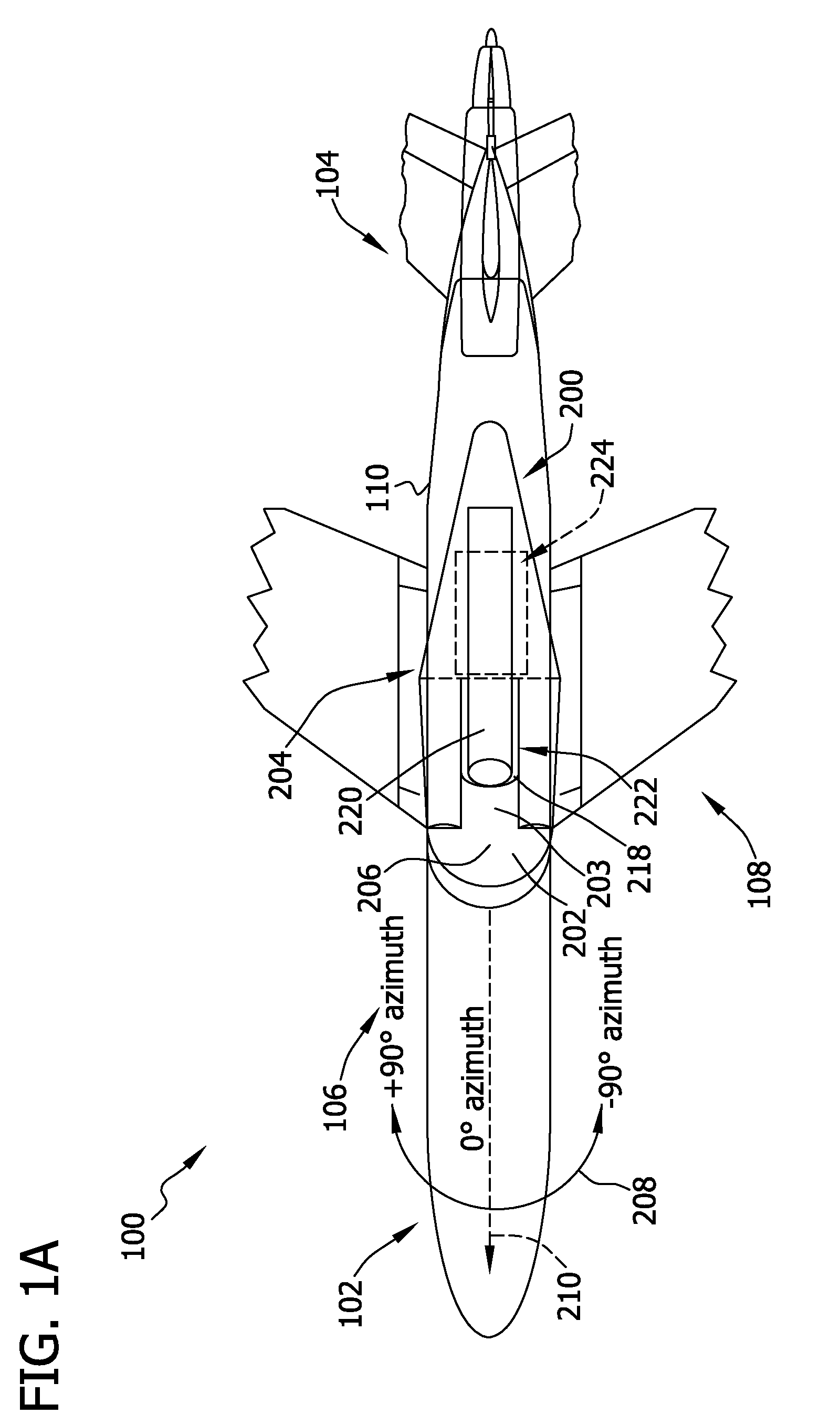
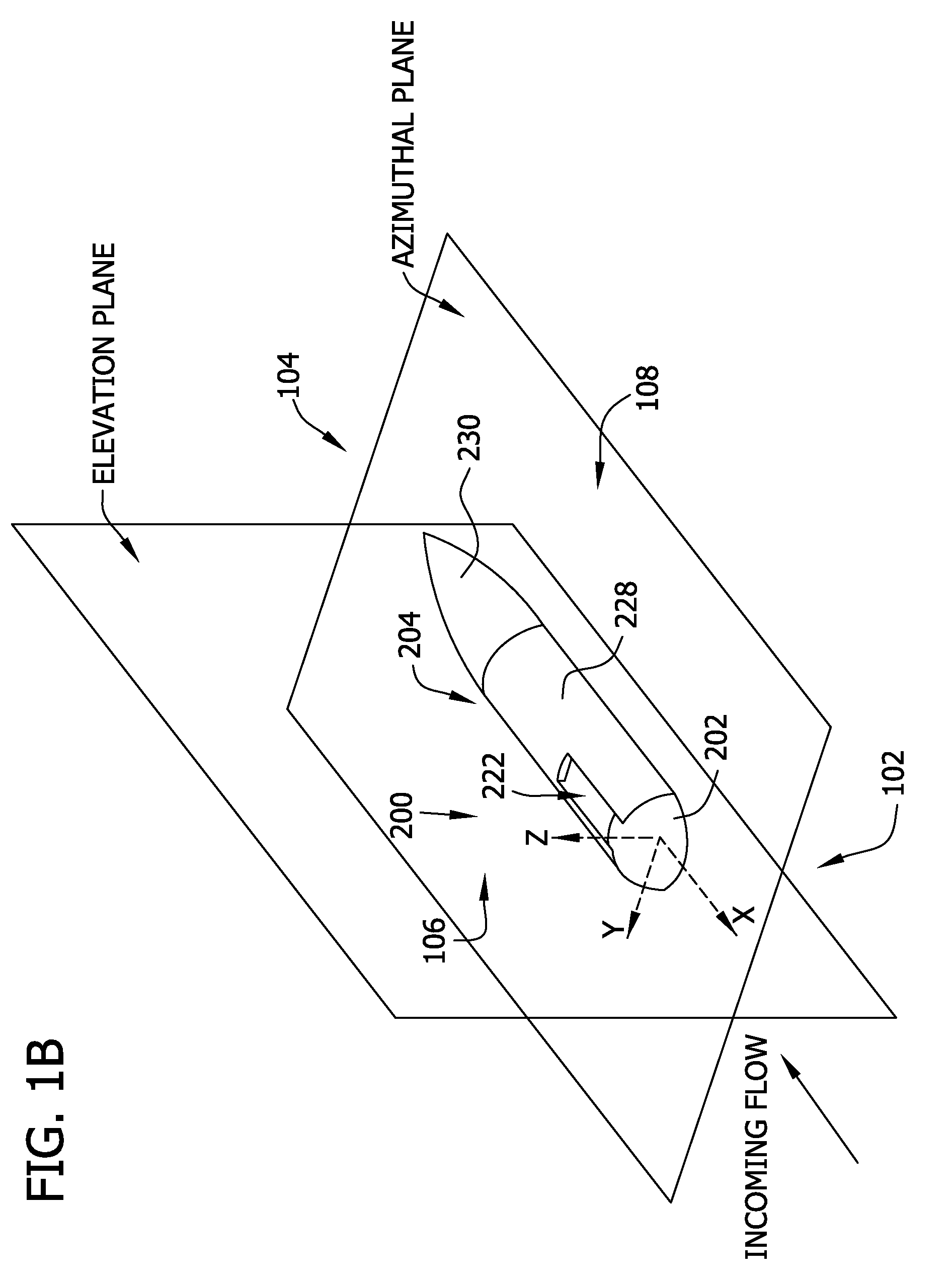
[0052]The effectiveness of a directed energy (laser or microwave) weapon or communication system mounted to an airborne platform, such as an aircraft, is significantly limited by aero-optic aberrations arising from density variations in air flowing over the aircraft. This lack of effectiveness is most limiting in the case where the directed energy laser system is pointed in the aft direction of the aircraft. The systems and methods described herein include a turret and fairing assembly that increases the effectiveness of a directed energy beam and increases a field of regard for propagation of the energy beam from an airborne platform flying at up to transonic speed. The example embodiment described herein incorporates a fairing section that includes a tuned cavity positioned between a tapered fairing portion and an aft fairing portion that excites a resonance mode of the airflow and causes the optical aberrations imposed by the shear layer to become more predictable over the entire...


PUM

PropertyMeasurementUnit
elevation anglesaaaaaaaaaa
azimuthal angleaaaaaaaaaa

Abstract

An aircraft turret and fairing assembly for facilitating transmission of a directed energy beam from a directed energy device includes a turret section for directing an energy beam. The assembly also includes a fairing section aft of and adjacent to the turret section. Each of the turret section and the aft fairing section are coupled to an aircraft. The assembly also includes at least one sensor for detecting air speed of the aircraft and air pressure. The turret section and the aft fairing section are configured and positioned relative to one another to direct airflow for generating an aeroacoustic resonance within a desired frequency range in an area aft of the turret section.

Description

CROSS REFERENCE TO RELATED APPLICATIONS[0001]This application claims the priority of Provisional Patent Application Ser. No. 61 / 024,353, which was filed on Jan. 29, 2008 and which is hereby incorporated by reference in its entirety.STATEMENT REGARDING FEDERALLY SPONSORED RESEARCH & DEVELOPMENT[0002]This invention was made with Government support under Government Contract No. FA9451-07-C-0029. The Government may have certain rights in this invention.BACKGROUND OF THE INVENTION[0003]This invention relates generally to aircraft sensor systems capable of detecting aeroacoustic resonances and disturbances and aero-optic aberrations in a fluid-dynamically active layer of airflow about an aircraft and methods to regularize such aberrations in characterized environments, and more specifically to utilizing such methods and systems with an aircraft for facilitating transmission of a directed energy (laser or microwave) beam from a directed energy device (weapon or communication system).[0004]...

Claims


Application Information

Patent Timeline
Patent Type & Authority Applications(United States)
IPC IPC(8): B64C1/00B64D7/00B64C1/14G06F19/00B23P11/00
CPCB64C7/00B64C23/06B64D7/06Y10T29/49826F41H13/005F41H13/0068Y02T50/162F41H13/0043Y02T50/10
Inventor CAIN, ALAN B.JUMPER, ERIC J.WITTICH, III, DONALD J.KERSCHEN, EDWARD J.CAVALIERI, DAVIDNG, T. TERRY
Owner INNOVATIVE TECH APPL COMPANY
Why Eureka
Try Eureka