Eureka AIR delivers breakthrough ideas for toughest innovation challenges, trusted by R&D personnel around the world.

Landing position determining method and device for processing-liquid ejection nozzles, and inkjet recording apparatus

Inactive Publication Date: 2009-10-01
FUJIFILM CORP
View PDF3 Cites 7 Cited by
  • Summary
  • Abstract
  • Description
  • Claims
  • Application Information

AI Technical Summary

Benefits of technology

[0019]It is an object of the present invention to solve the above-mentioned problems of the related arts and provide a landing position determining method and device for a processing-liquid ejection nozzle that can be applied to an inkjet recording apparatus having a recording head in which processing-liquid ejection nozzles and ink ejection nozzles are respectively aligned linearly and can determine a landing position of processing liquid from a processing liquid head with a stable and simple method, and provide the inkjet recording apparatus.

Problems solved by technology

Conventionally, when an image is printed on a recording medium in an inkjet recording apparatus, there has been a case in which water resistance of a recorded image is insufficient depending on a type of the recording medium.
In particular, when a color image is recorded, if a large quantity of ink is ejected on a recording medium in an attempt to print a high-density image, feathering may be caused depending on penetration of the ink into the recording medium.
On the other hand, if it is attempted to print a high-density image while suppressing the penetration, a blur may be caused among inks of different colors.
In both the cases, an image quality in printing a color image is substantially deteriorated.
Naturally, if the colored inks are deposited on the area on which the processing liquid is not deposited on the recording medium, fixing and agglomeration of the color materials of the colored inks is insufficient.
Therefore, desired ink density and a desired dot diameter are not obtained and the image quality is deteriorated.
In particular, when the inkjet head has a line head configuration, if a non-ejecting nozzle is present, the processing liquid is not deposited on an area on a recorded image and an image quality in the area is deteriorated, and hence the area appears like a line (streak) and is extremely conspicuous.
However, in the method disclosed in JP 08-118616 A, although a nozzle that is not ejecting the processing liquid can be detected, a method of determining a landing position of the processing liquid such that landing positions of the processing liquid and the ink coincide with each other is not disclosed, and hence it is impossible to prevent deterioration in an image quality of a recorded image due to ink fixing failure caused by the shift of the landing positions of the processing liquid and the ink.
In other words, the method cannot be applied to an apparatus in which processing-liquid ejection nozzles arranged in parallel in the scanning direction of the processing liquid head are moved in a direction orthogonal to the scanning direction of the processing liquid head to deposit the processing liquid on a recording medium.
Therefore, the method is time consuming and there is concern about an individual difference of each of the colored inks.

Method used


Image

  • Landing position determining method and device for processing-liquid ejection nozzles, and inkjet recording apparatus
  • Landing position determining method and device for processing-liquid ejection nozzles, and inkjet recording apparatus
  • Landing position determining method and device for processing-liquid ejection nozzles, and inkjet recording apparatus

Examples


first embodiment

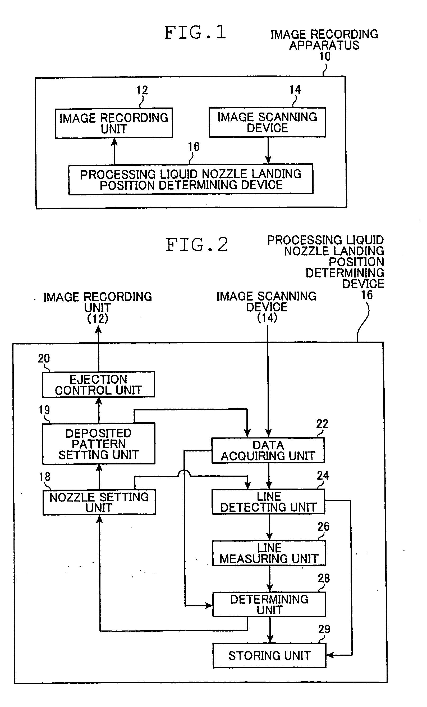
[0112]FIG. 1 is a diagram of a configuration of an image recording apparatus 10 to which the present invention is applied.

[0113]The image recording apparatus 10 is an ink jet recording apparatus that records, according to supplied image information, an image on a recording medium with the use of colored inks for forming an image and processing liquid for fixing the colored inks. The image recording apparatus 10 includes an image recording unit 12, an image scanning device 14, and a processing liquid nozzle landing position determining device 16 according to this embodiment of the present invention.

[0114]The image recording unit 12 includes an inkjet head (hereinafter, simply referred to as ejection head) having ink ejection nozzles (hereinafter, also simply referred to as ink nozzles) and processing-liquid ejection nozzles (hereinafter, also simply referred to as processing liquid nozzles) and conveying means for conveying a recording medium. The image recording unit 12 records an i...

second embodiment

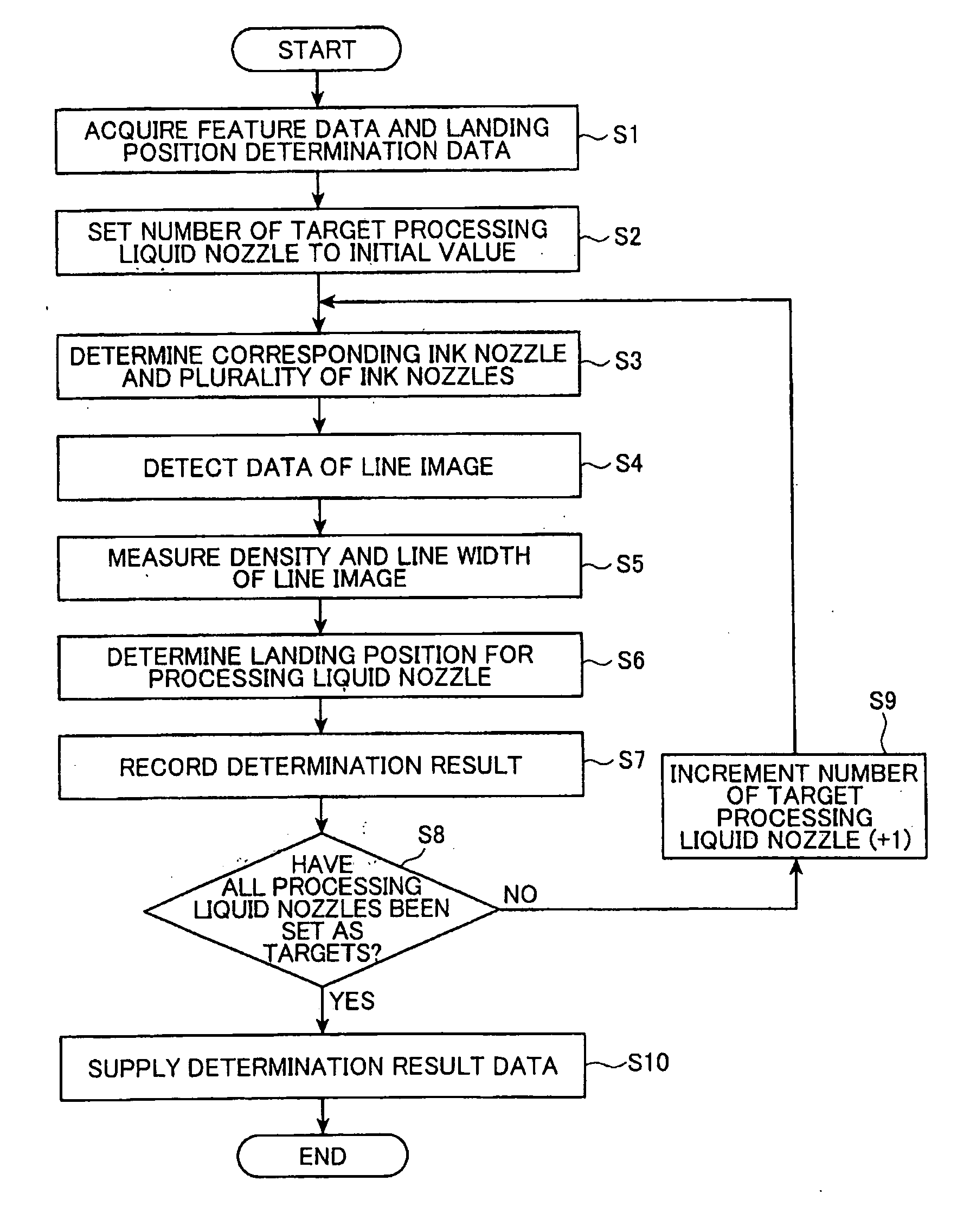
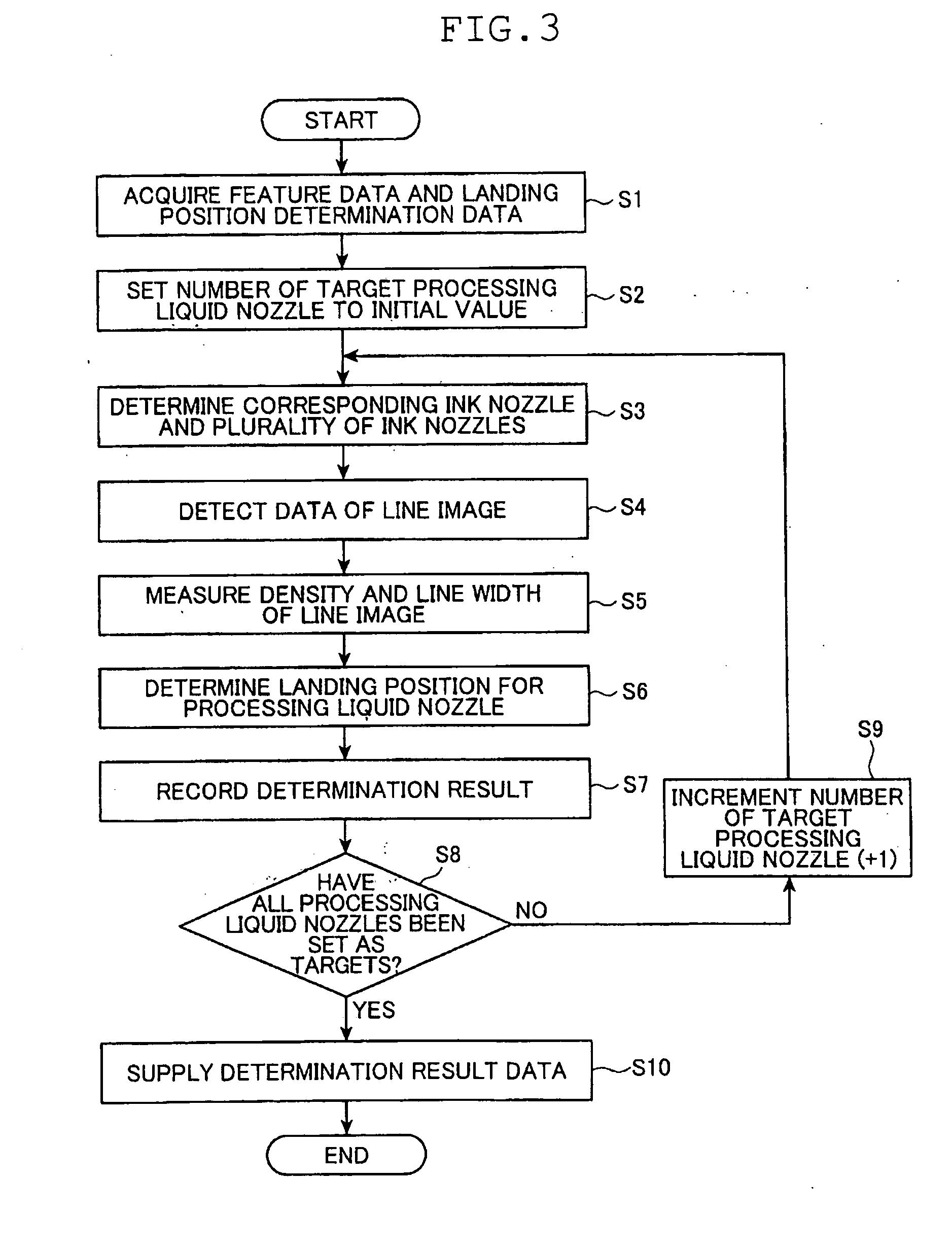
[0286]A landing position determining method for a processing liquid nozzle according to a second embodiment of the present invention is described below with reference to FIG. 16.

[0287]In the following description, differences from the first embodiment are mainly described. Description of components and processing same as those in the first embodiment is omitted to simplify description.

[0288]In the second embodiment, a processing liquid deposited pattern is set so that a line target area is formed which has density distribution (gradation) obtained by continuously depositing, while gradually changing the density of deposited processing liquid to be high or low in one direction, the processing liquid for a predetermined number of dots by each of processing-liquid ejection nozzles selected not to be adjacent to one another as landing position determination targets of the deposited processing liquid out of all processing-liquid ejection nozzles and so that the remaining processing-liqui...

third embodiment

A landing position determining method for a processing liquid nozzle according to the present invention is described below.

[0369]In the following description, differences from the first embodiment are mainly described. Description of components and processing same as those in the first embodiment is omitted to simplify description.

[0370]In the third embodiment, in order to set a processing liquid deposited pattern, for example, target processing liquid nozzles are selected out of all processing liquid nozzles not to be adjacent as landing position determination targets of processing liquid.

[0371]The processing liquid deposited pattern includes, in each of the processing liquid nozzles selected as the landing position determination targets, a processing liquid deposited area on which the processing liquid is continuously deposited a predetermined number of dots and a processing liquid non-deposited area on which the processing liquid is not continuously deposited the predetermined nu...


PUM


Abstract

A landing position determining method for processing-liquid ejection nozzles comprises: setting a specified processing liquid deposited pattern; ejecting the processing liquid from the processing-liquid ejection nozzles onto a recording medium to form the processing liquid deposited pattern; depositing the colored ink from a plurality of ink nozzles onto the processing liquid deposited pattern, and recording a plurality of linear colored ink images to form a processing liquid landing position determination pattern on the recording medium; detecting presence / absence of a change in at least one of densities and line widths of the plurality of linear colored ink images in the processing liquid landing position determination pattern, and determining, from at least one of density distribution and line width distribution in a linear colored ink image in which the change is present, a landing position for the processing-liquid ejection nozzle selected as the landing position determination targets.

Description

[0001]The entire contents of literature cited in this specification are incorporated herein by reference.BACKGROUND OF THE INVENTION[0002]The present invention relates to a landing position determining method and device for processing-liquid ejection nozzles, and more particularly, to a method and device for determining landing positions of the processing liquid ejected from processing-liquid ejection nozzles in an inkjet recording apparatus having nozzles that eject colorless and transparent processing liquid for agglomerating colored inks.[0003]Conventionally, when an image is printed on a recording medium in an inkjet recording apparatus, there has been a case in which water resistance of a recorded image is insufficient depending on a type of the recording medium.[0004]In particular, when a color image is recorded, if a large quantity of ink is ejected on a recording medium in an attempt to print a high-density image, feathering may be caused depending on penetration of the ink ...

Claims


Application Information

Patent Timeline
IPC IPC(8): B41J29/38
CPCB41J29/393B41J2/2114
Inventor YAMAZAKI, YOSHIROU
Owner FUJIFILM CORP
Why Eureka
Eureka Blog
Learn More