Inkjet printer

a technology of inkjet printers and printers, which is applied in the direction of printing, other printing apparatus, etc., can solve the problems of uneven dryness of ink adhesion to the underlying previous piece of paper, deterioration of the print quality of uneven dryness of the ink adhesion to the underlying piece of paper, etc., to achieve the effect of uniform air in the space, easy removal, and high degree of freedom of placemen

Inactive Publication Date: 2009-10-01
NORITZ CORP
View PDF11 Cites 12 Cited by
  • Summary
  • Abstract
  • Description
  • Claims
  • Application Information

AI Technical Summary

Benefits of technology

[0010]The present invention has been made in view of the foregoing points and, therefore, an object of the invention is that even if heat produced in the drying part during the warm-up operation is transferred to the space in the printing part, the occurrence of temperature variations in the space is prevented with a simple structure.
[0012]With the above configuration, during the warm-up operation, the agitator agitates the air in the space in the printing part. Thus, the temperature of the space can be made uniform and the occurrence of temperature variations in the space can be prevented with a simple structure. As a result, upon printing after the end of the warm-up operation, no temperature variations occur in the space. Therefore, the temperature detected by a temperature sensor disposed such as on the print head can be approximately equal to the actual temperature of each ink-flight space. Furthermore, even if the print head includes a plurality of head units arranged side by side in the direction of paper conveyance, it can be prevented that a temperature difference occurs between the ink-flight spaces for the plurality of head units. Accordingly, the inkjet printer can maintain a good print quality.
[0014]Thus, the suction device, which is used during printing to hold by suction the paper on the support surface of the platen, can function also as an agitator by operating it also during the warm-up operation. The suction device is originally used in order to ensure the flatness of the paper during printing and thereby enhance the print quality. In inkjet printers including such a suction device, the suction device can be used also as an agitator and, therefore, the occurrence of temperature variations in the space in the printing part can be prevented at low cost and with a simple structure.
[0016]Such a fan has a high degree of freedom of placement. Therefore, the fan can be easily disposed at a point where the air in the space can be effectively made uniform. This ensures that the inkjet printer maintains a good print quality.

Problems solved by technology

The reason for this is that if a next printed piece of paper is laid on a previous printed piece of paper with ink thereon not yet dried, the next piece of paper brushes against the wet ink on the underlying previous piece of paper, whereby the print quality of the underlying piece of paper is deteriorated and the back of the overlying piece of paper is stained with ink adhering thereto.
In addition, the next piece of paper overlaid on the previous piece of paper causes uneven dryness of ink adhering to the underlying previous piece of paper.
Such uneven dryness also deteriorates the print quality.
In such a case, however, heat produced by the drying part may be transferred to the space in the printing part to cause temperature variations in the space.
This leads to misalignment between the landing points of ink from the plurality of head units and thereby deteriorates the print quality.

Method used


Image

  • Inkjet printer
  • Inkjet printer
  • Inkjet printer

Examples


Embodiment Construction

[0026]Example embodiments will be explained below with reference to the drawings. The following example embodiments are merely illustrative in nature and are not intended to limit the scope, applications and use of the invention.

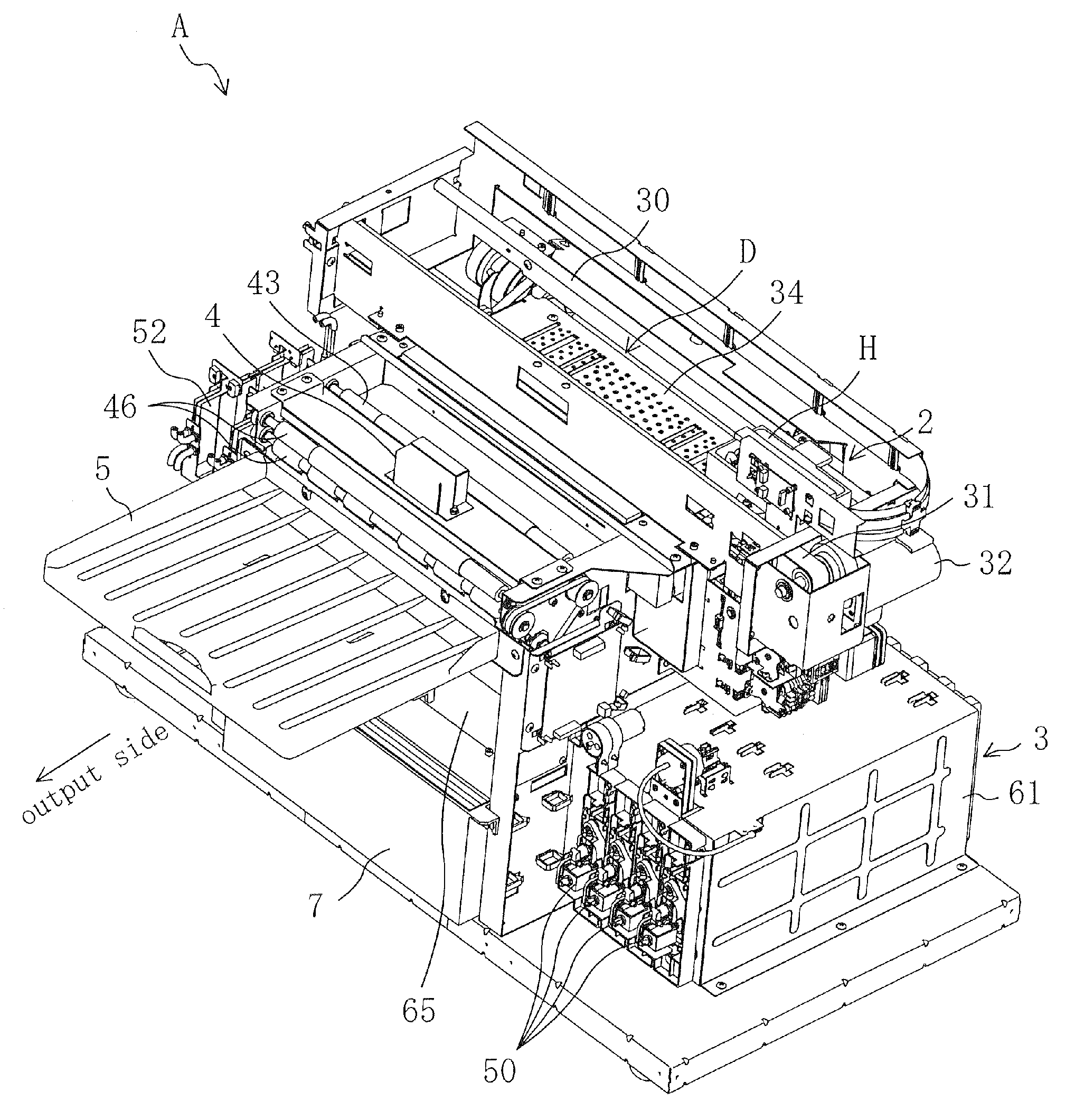
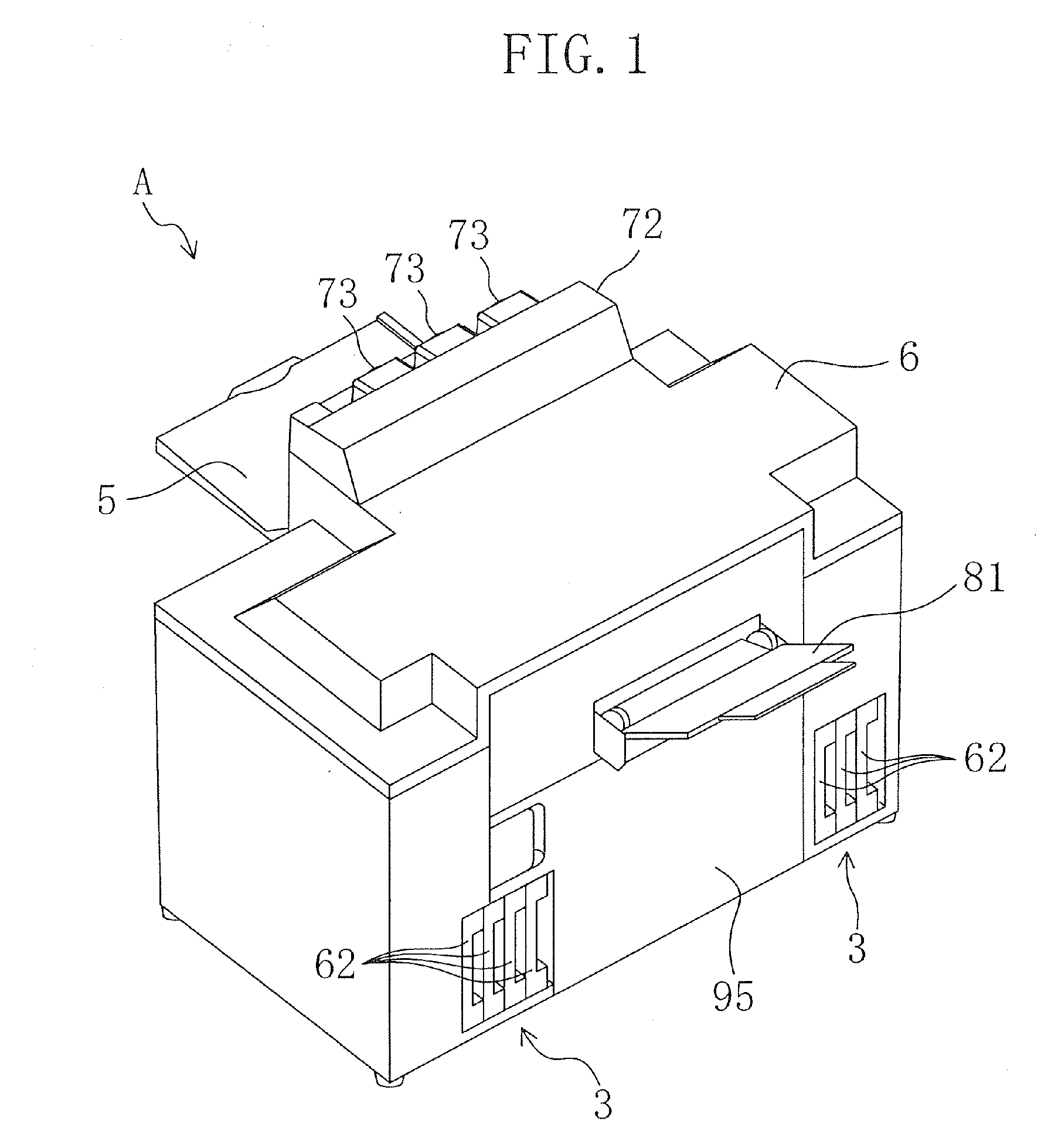
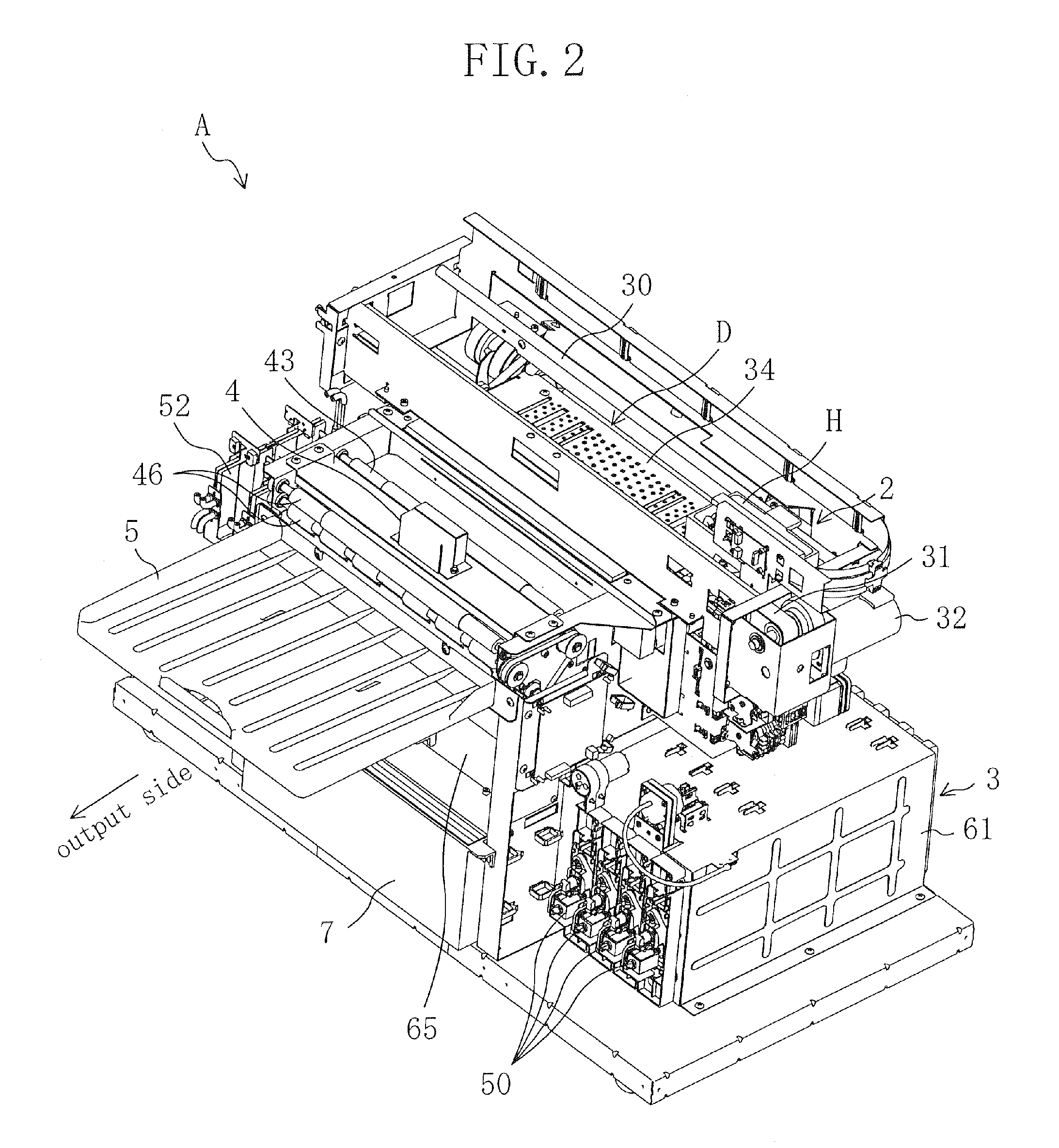
[0027]FIG. 1 shows the appearance of an inkjet printer A according to an example embodiment, and FIGS. 2 to 7 show the internal structure of the inkjet printer A. The inkjet printer A is used for a photographic printing system and, for example, used for printing photographic images on printing paper P1 or P2 based on image data transmitted via a communication cable from a reception block for obtaining the image data and correcting it as necessary. More specifically, the inkjet printer A can perform an automatic printing and a manual-feed printing. In the automatic printing, the inkjet printer A pulls out one end of a long roll of printing paper P2 and prints an image on the printing surface of the roll of printing paper P2 (hereinafter, referred to as a pape...


PUM


Abstract

An inkjet printer includes: a printing part including a print head for ejecting ink to paper to print an image on the paper; a drying part including a heater for drying the ink adhering to the paper printed by the print head; and an agitator for agitating the air in the space in the printing part during a warm-up operation involving raising the temperature of the heater.

Description

CROSS-REFERENCE TO RELATED APPLICATION[0001]This application claims priority under 35 USC 119 to Japanese Patent Application No. 2008-079593 filed on Mar. 26, 2008, the entire contents of which are incorporated herein by reference.BACKGROUND[0002]The techniques disclosed in this specification relate to inkjet printers that include: a printing part including a print head for ejecting ink to paper to print an image on the paper; and a drying part including a heater for drying the ink adhering to the paper printed by the print head.[0003]Generally, inkjet printers include a printing part with a print head for ejecting ink to paper to print an image on the paper. The print head ejects ink to paper conveyed to the printing part by a paper conveyance mechanism while reciprocating along a direction (main scanning direction) orthogonal to the direction of paper conveyance (sub-scanning direction) and thereby prints an image (including characters; the same applies hereinafter) on the paper. ...

Claims


Application Information

Patent Timeline
Patent Type & Authority Applications(United States)
IPC IPC(8): B41J2/01
CPCB41J11/002B41J29/377B41J29/02B41J11/0085B41J11/00222
Inventor TSUJI, MASAAKITANAKA, YASUHIRO
Owner NORITZ CORP
Why Eureka
Try Eureka