Imaging device

a technology of a zoomer and a lens is applied in the field of imaging devices, which can solve the problems of difficult introduction and facial image lying off the zoom area, and achieve the effects of reducing processing, improving operability, and reducing the zoom magnification of the zoomer

Inactive Publication Date: 2009-10-01
SANYO ELECTRIC CO LTD
View PDF15 Cites 25 Cited by
  • Summary
  • Abstract
  • Description
  • Claims
  • Application Information

AI Technical Summary

Benefits of technology

[0010]According to the first invention, the zoomed object image of the zoom area of the object scene image is displayed on the first screen, and the information indicating the position of the specific image detected from the object scene image with respect to the zoom area is displayed on the second screen. The specific image here can also be detected from the part not belonging to the zoom area of the object scene image, and therefore, it is possible to produce information indicating the position of the specific image with respect to the zoom area. Accordingly, the user can know a positional relation between the specific object and the first screen, that is, a positional relation between the specific image and the zoom area with reference to the position information on the second screen. Thus, it is possible to easily introduce the specific image into the zoom area smoothly.
[0042]According to the fourteenth invention, it is also possible to smoothly introduce the specific image into the zoom area similar to the ninth invention.

Problems solved by technology

However, when the zoom magnification becomes high, a slight movement of the optical axis due to the movement of the body of the user causes the facial image to lie off the zoom area.
When the facial image extends off the zoom area, it is not easy to introduce this into the zoom area again.

Method used


Image

  • Imaging device
  • Imaging device
  • Imaging device

Examples


first embodiment

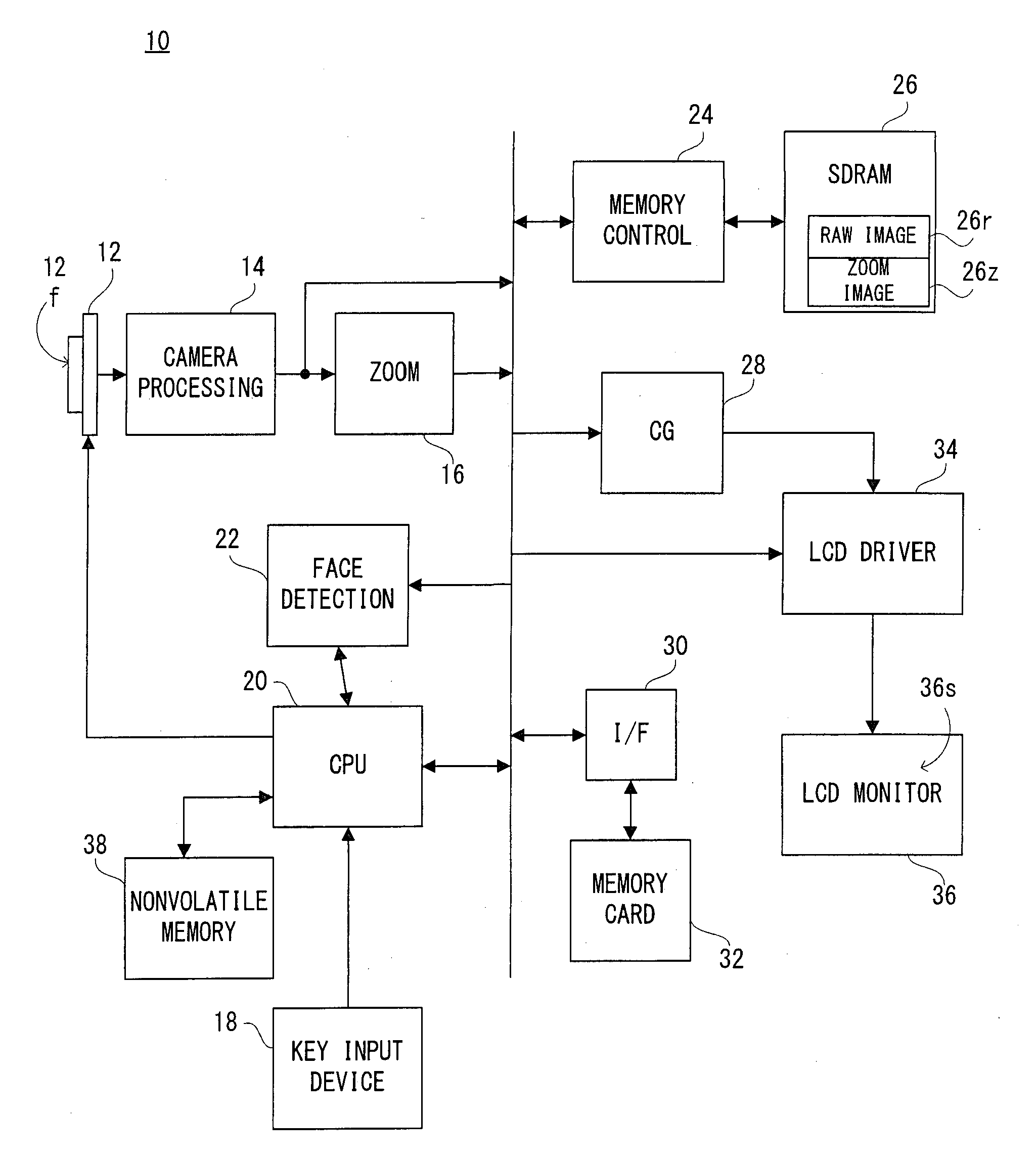
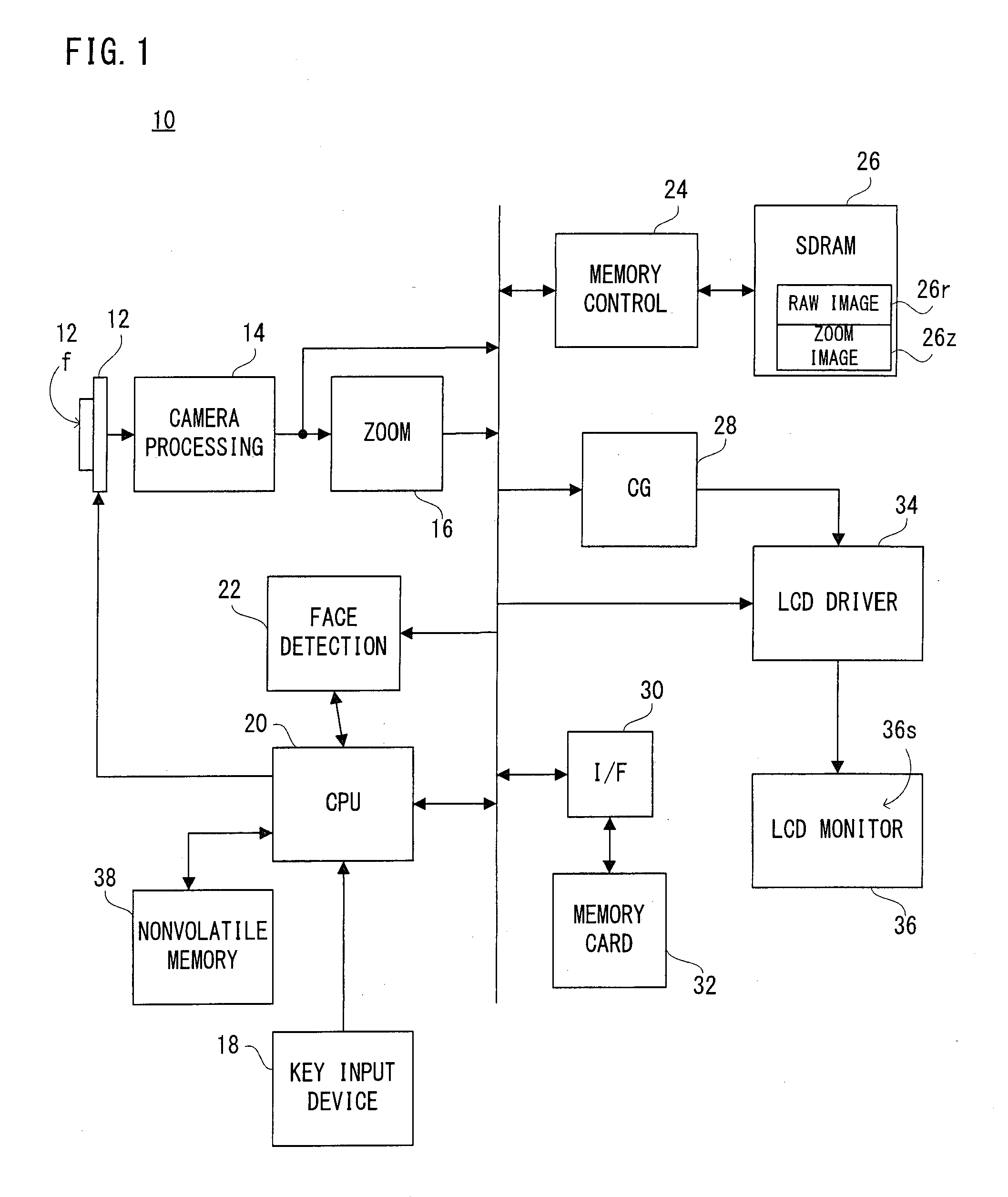
[0066]Referring to FIG. 1, a digital camera 10 of this embodiment includes an image sensor 12. An optical image of an object scene is irradiated onto the image sensor 12. An imaging area 12f of the image sensor 12 includes charge-coupled devices of 1600×1200 pixels, for example, and on the imaging area 12f, electric charges corresponding to the optical image of the object scene, that is, a raw image signal of 1600×1200 pixels is generated by a photoelectronic conversion.

[0067]When a power source is turned on, the CPU 20 instructs the image sensor 12 to repetitively execute a pre-exposure and a thinning-out reading in order to display a real-time motion image of the object, that is, a through-image on an LCD monitor 36. The image sensor 12 repetitively executes a pre-exposure and a thinning-out reading of the raw image signal thus generated in response to a vertical synchronization signal (Vsync) generated every 1 / 30 second. A raw image signal of 320×240 pixels corresponding to the o...

second embodiment

[0114]The configuration of this embodiment is the same or similar to that of the first embodiment, and therefore, the explanation is omitted by using FIG. 1 for help. The basic operation (normal mode) is also common, and the explanation therefor is omitted. The feature of this embodiment is in an “automatically following+cut-out position displaying mode”, but this mode is partially common to the “face position displaying mode 2” in the first embodiment, and the explanation in relation to the common part is omitted. Additionally, FIG. 1 and FIG. 11-FIG. 15 are referred below.

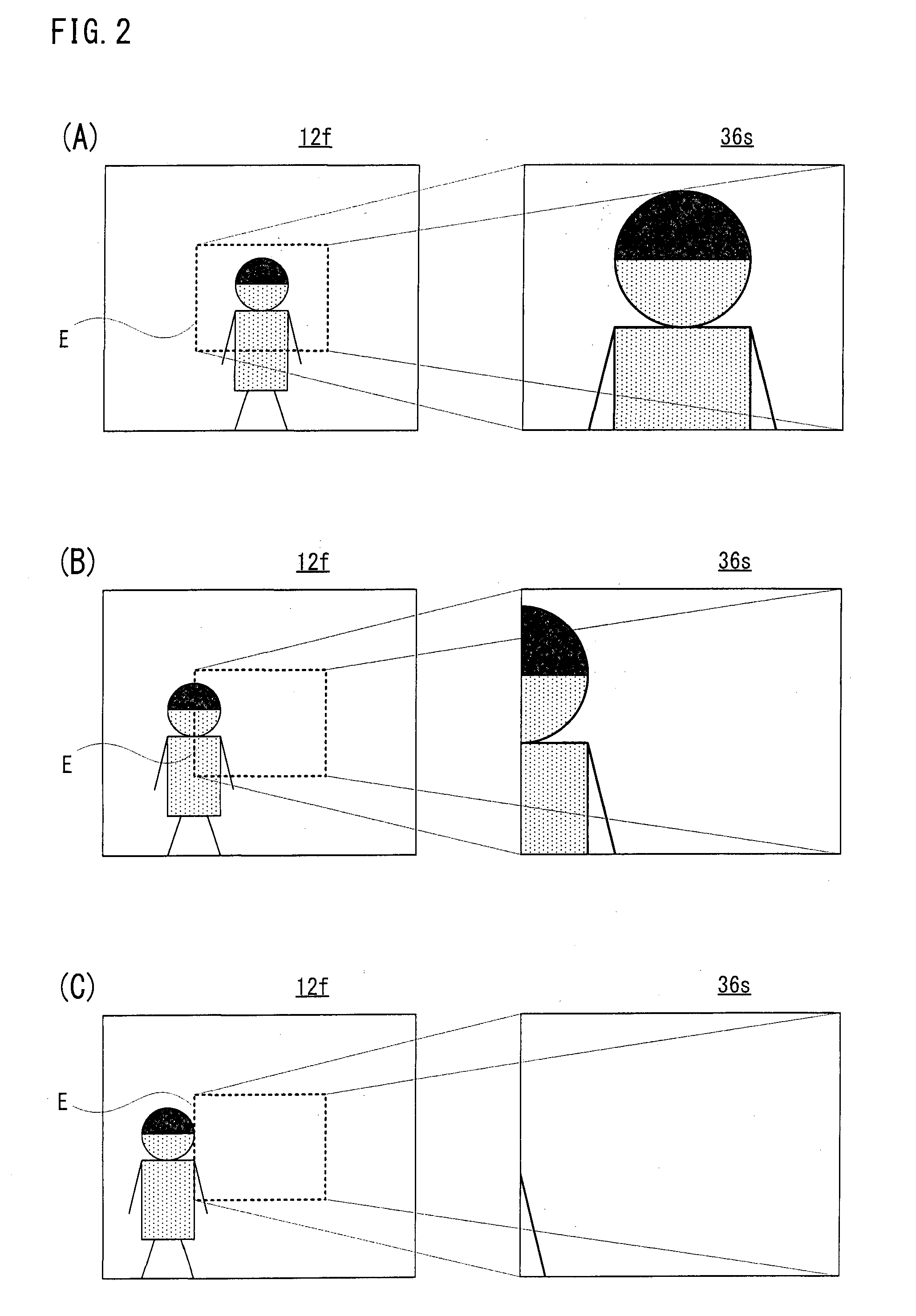
[0115]When the “automatically following+cut-out position displaying mode” is selected by the key input device 18, the mini-screen MS2 including the area symbol ES representing the position of the zoom area E is immediately displayed, and the display of the mini-screen MS2 is continued until another mode is selected. That is, in this mode, as shown in FIG. 11(A)-FIG. 11(C), the mini-screen MS2 is always displayed ...

third embodiment

[0130]The configuration of this embodiment is the same or similar to that of the first embodiment, and therefore, the explanation is omitted by using FIG. 1 for help. The basic operation (normal mode) is also common, and the explanation therefor is omitted. The feature in this embodiment is in a “face direction displaying mode”, but this mode is partially common to the “face position displaying mode 1” in the first embodiment, and therefore, the explanation in relation to the common part is omitted. Additionally, FIG. 1 and FIG. 16-FIG. 20 are referred below.

[0131]When the “face direction displaying mode” is selected by the key input device 18, in a case that the facial image which is being noted lies off the monitor screen 36s, an arrow Ar representing the direction in which the facial image exists is displayed on the monitor screen 36s as shown in FIG. 16(A)-FIG. 16(C).

[0132]More specifically, as shown in FIG. 17(A), the part except for the zoom area E of the object scene correspo...


PUM


Abstract

A digital camera as one example of an imaging device includes an image sensor, and by utilizing this, an optical image of an object scene is repeatedly captured. A partial object scene image belonging to a zoom area of the object scene image produced by the image sensor is subjected to zoom processing by a zooming circuit, and the obtained zoomed object image is displayed on a monitor screen of an LCD by an LCD driver. A CPU detects a facial image from the produced object scene image through a face detecting circuit, calculates the position of the detected facial image with respect to the zoom area, and displays the position information indicating the calculated position on a mini-screen within the monitor screen by controlling a character generator and the LCD driver.

Description

CROSS REFERENCE OF RELATED APPLICATION[0001]The disclosure of Japanese Patent Application No. 2008-86274 is incorporated herein by reference.BACKGROUND OF THE INVENTION[0002]1. Field of the Invention[0003]The present invention relates to an imaging device. More specifically, the present invention relates to an imaging device having an electronic zooming function and a face detecting function.[0004]2. Description of the Related Art[0005]In zoom photographing, a user generally moves an optical axis of an imaging device with reference to the monitor screen in a state that the zoom is canceled, and introduces an object which is being noted, face, for example, into approximately the center of the object scene. Then, the optical axis of the imaging device is fixed, and the zoom operation is performed. Thus, it is possible to easily introduce the face image into the zoom area.[0006]However, when the zoom magnification becomes high, a slight movement of the optical axis due to the movement ...

Claims


Application Information

Patent Timeline
Patent Type & Authority Applications(United States)
IPC IPC(8): H04N5/76H04N5/232
CPCH04N5/23219H04N5/23296H04N5/23293H04N23/61H04N23/611H04N23/635H04N23/69
Inventor SAITO, SATOSHIKOSHIYAMA, SEIJI
Owner SANYO ELECTRIC CO LTD
Why Eureka
Try Eureka