Lens assembly and imaging device

a technology of assembly and lens, applied in the direction of mountings, optics, instruments, etc., can solve the problems of lens movement, inability to recognize whether or not an adhesive agent effectively infiltrates the adhesive layer, and complicated mechanism of the lens fram

Active Publication Date: 2009-10-01
NANCHANG O FILM OPTICAL ELECTRONICS TECH CO LTD
View PDF3 Cites 14 Cited by
  • Summary
  • Abstract
  • Description
  • Claims
  • Application Information

AI Technical Summary

Benefits of technology

[0008]An object of an illustrative, non-limiting embodiment of the present invention is to provide a compact lens assembly in which the b...

Problems solved by technology

However, in such a structure, when the lenses are bonded and fixed, since adhesive agent applying parts as described in JP-A-2001-027723 need to be provided in the lens frame, a mechanism of the lens frame is complicated and enlarged.
Further, in the structure disclosed in JP-A-2001-027723, since adhesive layers for bonding the lenses to the lens frame are not seen from a front surface, whether or not an adh...

Method used


Image

  • Lens assembly and imaging device
  • Lens assembly and imaging device
  • Lens assembly and imaging device

Examples


Embodiment Construction

[0025]According to an exemplary embodiment of the invention, it is possible to provide a compact lens assembly in which the bonded state of the lens to a lens frame can be recognized from an external part, and to provide an imaging device having the lens assembly.

[0026]Now, an exemplary embodiment of the present invention will be described below.

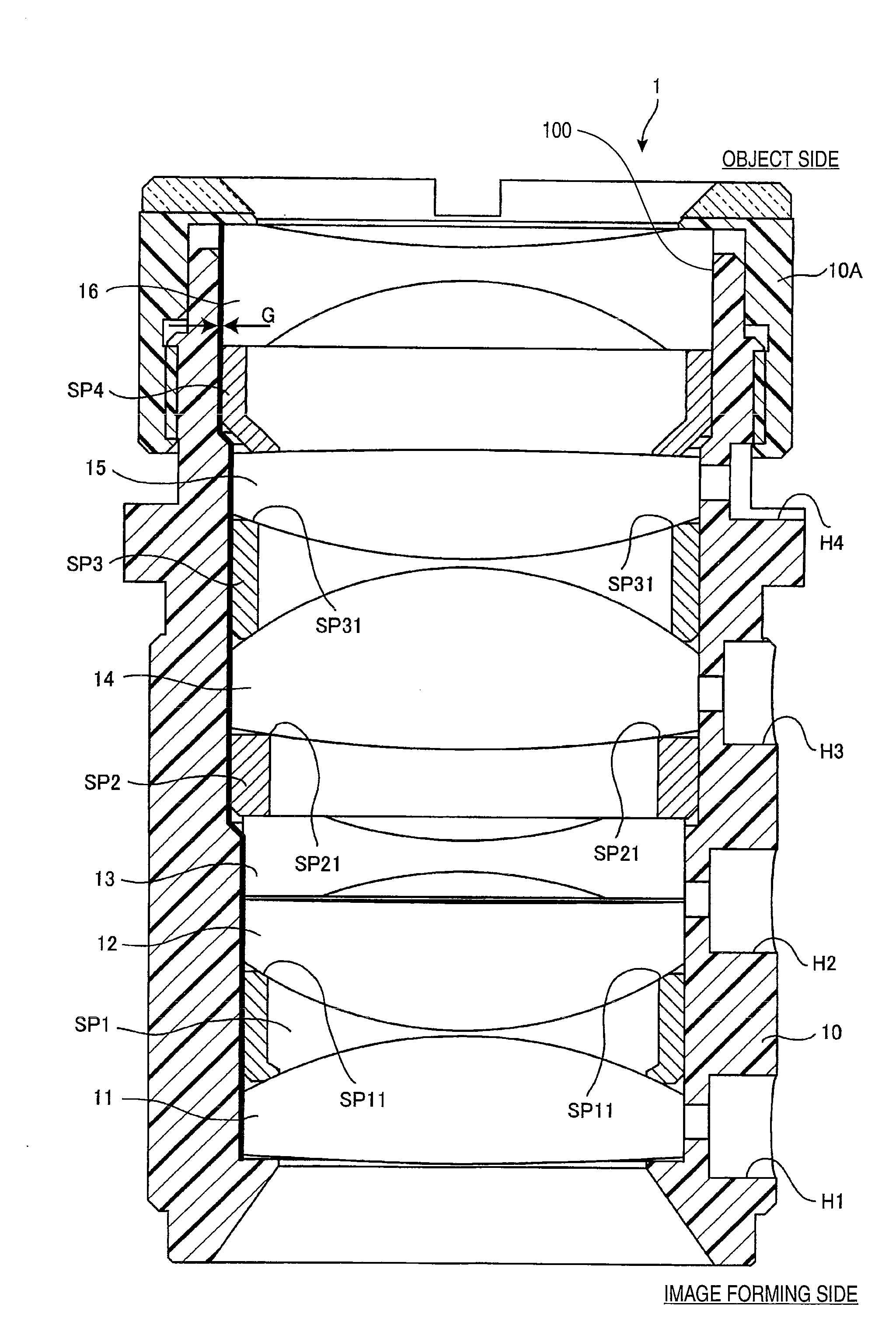
[0027]FIG. 1 is a diagram showing a surface of a lens assembly 1 according to an exemplary embodiment of the present invention, which is taken along an optical axis of a lens and seen from a side part. An upper part of FIG. 1 is an object side and a lower part of FIG. 1 is an image forming side.

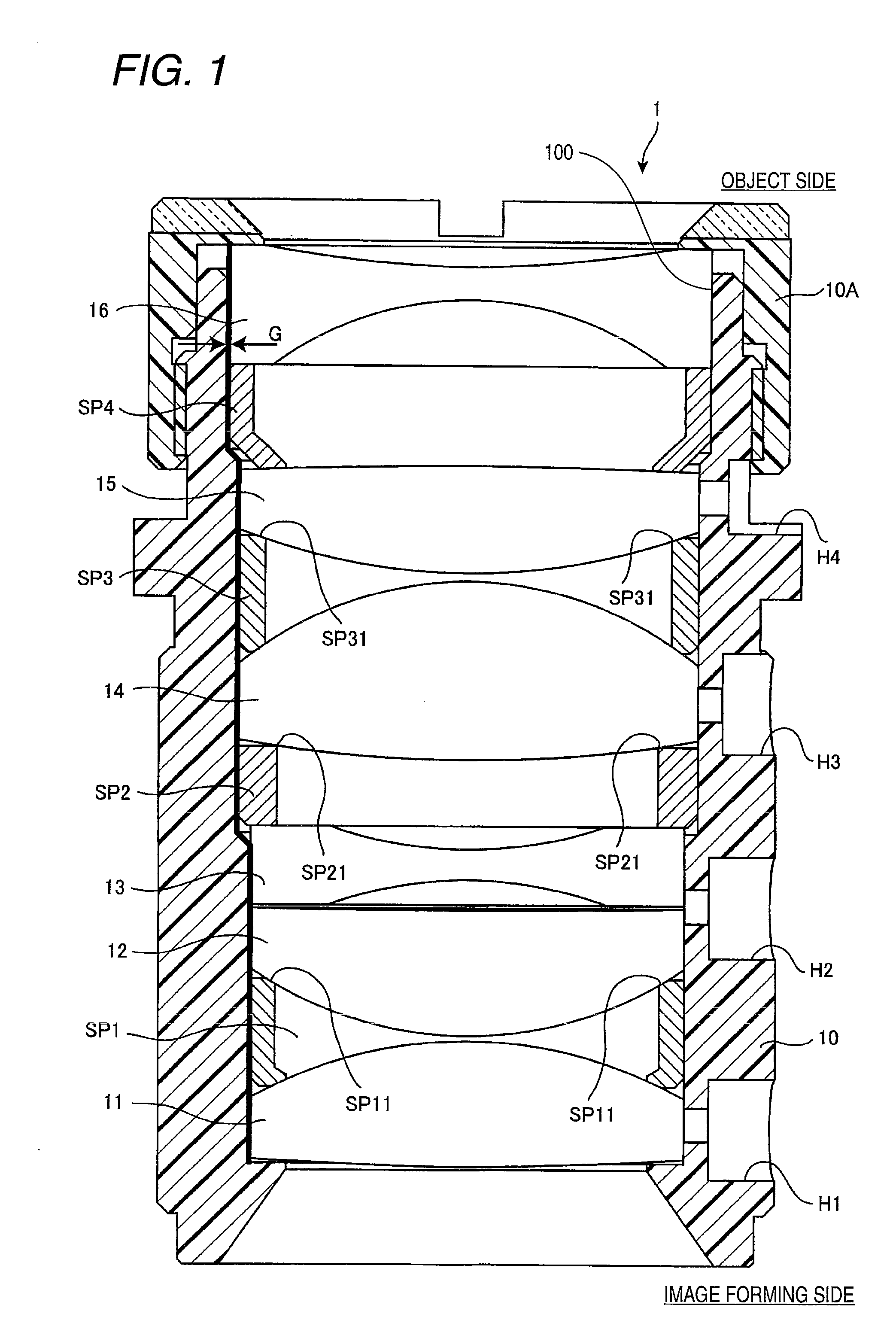
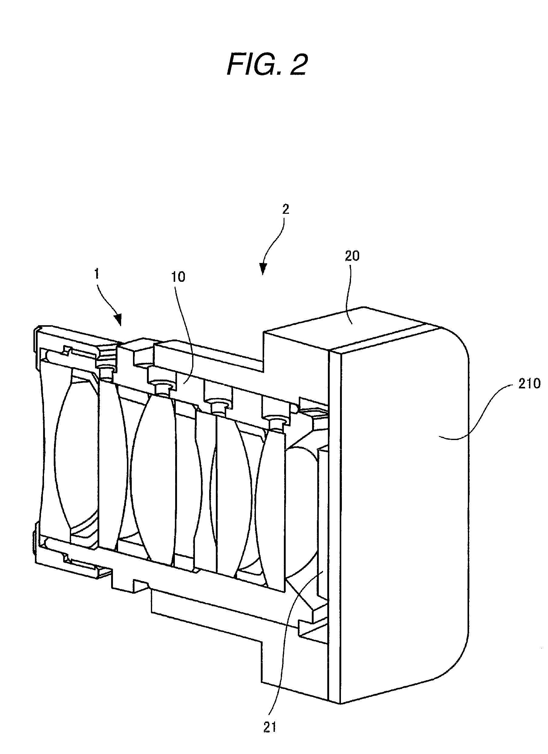
[0028]FIG. 1 shows a lens assembly 1 provided with a lens frame 10 having a hollow part 100 into which space rings SP1 to SP4 for determining spaces between lenses and a plurality of lenses 11 to 16 are inserted in prescribed order. In FIG. 1, six lenses including two concave lenses 13 and 16 and four convex lenses 11, 12, 14 and 15 are combined toget...


PUM


Abstract

A lens assembly is provided and includes: a lens frame; and a lens frame having a hollow part into which the lens is inserted. The lens frame has a bonding hole into which an adhesive agent is injected for bonding and fixing to the lens frame the lens inserted into the lens frame and which passes through an outer wall of the lens frame and an inner wall of the hollow part.

Description

[0001]This application is based on and claims priority under 35 U.S.C §119 from Japanese Patent Application No. 2008-088528, filed on Mar. 28, 2008, the entire disclosure of which is herein incorporated by reference.BACKGROUND OF THE INVENTION[0002]1. Field of the Invention[0003]The present invention relates to a lens assembly in which a lens is inserted into a lens frame, and an imaging device having the lens assembly.[0004]2. Description of Related Art[0005]Recently, cameras for watching places of the dead angle for drivers have been equipped with motor vehicles. Further, in department stores or mansions, many fixed-point cameras for monitoring have been arranged.[0006]Since these cameras are frequently provided outside, such a strict waterproof performance or a dustproof function as to withstand an outdoor environment are required. Accordingly, a certain lens assembly applied to such a camera has a structure that space rings for determining spaces between a plurality of lenses ar...

Claims


Application Information

Patent Timeline
IPC IPC(8): G02B7/02
CPCG02B7/025G02B7/021
Inventor SAKAI, YUYAOHNO, MISTUHIRO
Owner NANCHANG O FILM OPTICAL ELECTRONICS TECH CO LTD
Why Eureka
Try Eureka