Light pipe, illumination optical system and image projection device

a technology of optical system and light pipe, which is applied in the direction of instruments, lighting and heating equipment, fibre light guides, etc., can solve the problems of obstructing the formation of the whole device in a compact shape, increasing the weight and volume of the light source, and reducing the utilization efficiency of light, so as to prevent the effect of lowering the light utilization efficiency

Inactive Publication Date: 2009-10-01
BROTHER KOGYO KK
View PDF10 Cites 21 Cited by
  • Summary
  • Abstract
  • Description
  • Claims
  • Application Information

AI Technical Summary

Problems solved by technology

However, such a light source requires large amount of electricity and also requires a cooling device to cope with the elevation of temperature and hence, a weight and a volume of the light source are increased, and such increase of the weight and the volume obstructs the formation of the whole device in a compact shape.
However, light radiated from the LED exhibits low directivity and hence, a reflector and a focusing lens system become necessary, and the brightness of the light in the light radiation direction is not always uniform.
Further, when the brightness irregularities are present with respect to the radiation direction, the brightness irregularities are generated on the projection surface thus lowering image quality.
Particularly, in case the illumination light-source device 50 is used in a projector, an allowable incident angle of the projection lens is smaller than a light emission angle of the LED and hence, light radiated from the light pipe at a radiation angle larger than an allowable incident angle is not projected from the projection lens thus causing a loss.

Method used


Image

  • Light pipe, illumination optical system and image projection device
  • Light pipe, illumination optical system and image projection device
  • Light pipe, illumination optical system and image projection device

Examples


Embodiment Construction

[0022]Hereinafter, the constitution of the present invention is explained in detail in conjunction with attached drawings.

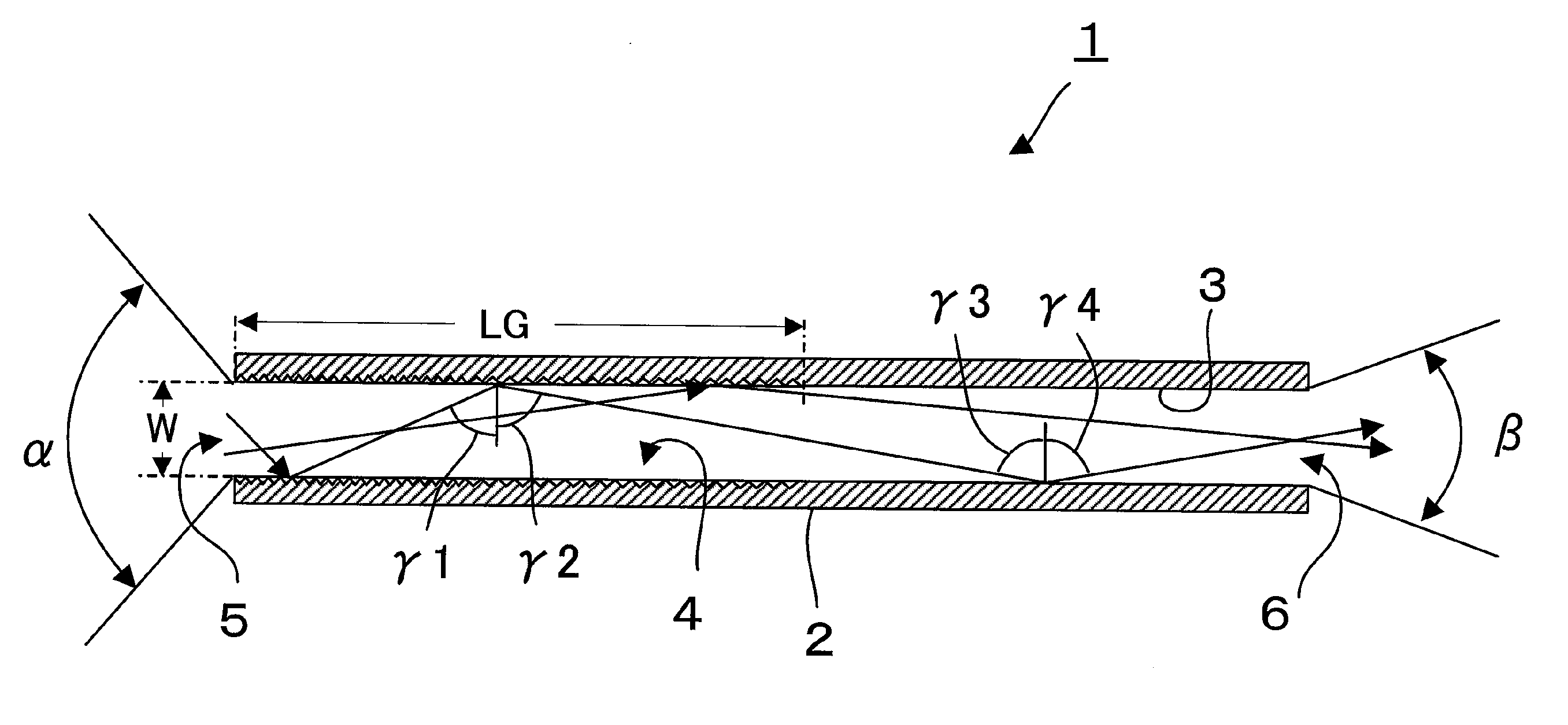
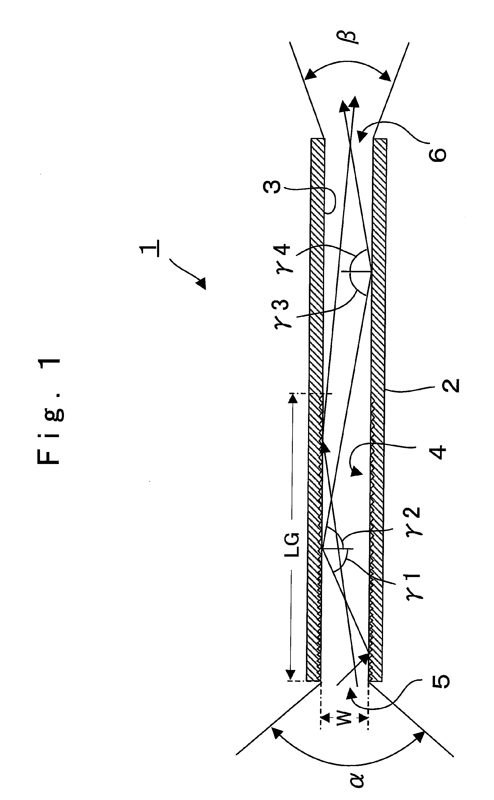
[0023]FIG. 1 is a schematic longitudinal cross-sectional view showing the constitution of a light pipe 1 according to an embodiment of the present invention. The light pipe 1 is formed of a light guide body 2 having a cylindrical shape and having a hollow inside. An inner wall surface of the light guide body 2 forms a side wall surface 3, and the side wall surface 3 is constituted of a reflection surface which reflects light. The light guide body 2 allows the incidence of light therein from an incident opening 5 and radiates the incident light from a radiation opening 6. A diffraction portion 4 is formed on the side wall surface 3 of the light guide body 2 on an incident opening 5 side. Assuming a maximum angle of an optical flux which is incident on the light pipe 1 in a spreading manner as an incident angle α, light which is incident on the light pipe 1 at the ...


PUM


Abstract

In a light pipe which allows light from a light source to be incident on the light pipe from an incident opening to be repeatedly reflected on a side wall surface of the light pipe, and to be radiated from a radiation opening, it is possible to radiate illumination light having high directivity and uniform brightness distribution thus radiating light while enhancing utilization efficiency of light. A diffraction portion is formed in a region on an incident opening side of a side wall surface of a light pipe. In the diffraction portion, light is reflected such that a reflection angle with respect to the side wall surface is larger than an incident angle with respect to the side wall surface, and a radiation angle of light radiated from a radiation opening is smaller than an incident angle of light incident on the light pipe from an incident opening.

Description

CROSS-REFERENCE TO RELATED APPLICATION(S)[0001]This application is based on and claims the benefit of priority from Japanese Patent Application No. 2008-088191 filed on Mar. 28, 2008; the entire contents of which are incorporated herein by reference.BACKGROUND[0002]1. Field[0003]The present invention relates to a light pipe which introduces light therein from one end thereof and radiates the light from another end thereof, and an illumination optical system and an image projection device which uses such a light pipe.[0004]2. Description of the Related Art[0005]There has been popularly used an image projection device which radiates light from a light source to an optical modulation element such as a liquid crystal display element or a DMD (digital micro mirror device) element, and projects an image on a screen. As a light source which radiates light to the optical modulation element, a halogen lamp, a high-pressure mercury-vapor lamp or the like has been used. However, such a light s...

Claims


Application Information

Patent Timeline
Patent Type & Authority Applications(United States)
IPC IPC(8): F21V7/04G03B21/00
CPCG02B6/0006G03B21/00G02B6/0096G02B6/0008G03B21/005
Inventor HAYAKAWA, KAZUHIROIKEDA, YUJI
Owner BROTHER KOGYO KK
Why Eureka
Try Eureka