
Optical recording/reproducing apparatus

a recording/recording and recording technology, applied in the direction of data recording, instruments, disposition/mounting of heads, etc., can solve the problems of unstable decelerating driving, difficult to search optimal driving time and optimal driving amount, and failure to jump to a target track, etc., to achieve stable implementation of acceleration and decelerating driving at a short time period

Inactive Publication Date: 2009-10-01
SAMSUNG ELECTRONICS CO LTD
View PDF9 Cites 0 Cited by
  • Summary
  • Abstract
  • Description
  • Claims
  • Application Information

AI Technical Summary

Benefits of technology

[0013]The present general inventive concept provides an optical recording / reproducing apparatus which can achieve track jump at a low speed by outputting an accelerating and decelerating driving amount as a pulse width modulation (PWM) signal during a track jump and thus stably implementing accelerating and decelerating driving at a short time period.
[0014]The present general inventive concept also provides an optical recording / reproducing apparatus which can stably implement track jump by minutely dividing a speed variation amount during a track jump and thus reducing a speed variation during tracking servo control.
[0015]The present general inventive concept also provides an optical recording / reproducing apparatus which can achieve minute adjustment even at a low resolution of a DAC by using a magnitude and duty of an accelerating and decelerating driving amount during track jump of a high-density disc.
[0029]The speed variation may be reduced during a tracking servo control.

Problems solved by technology

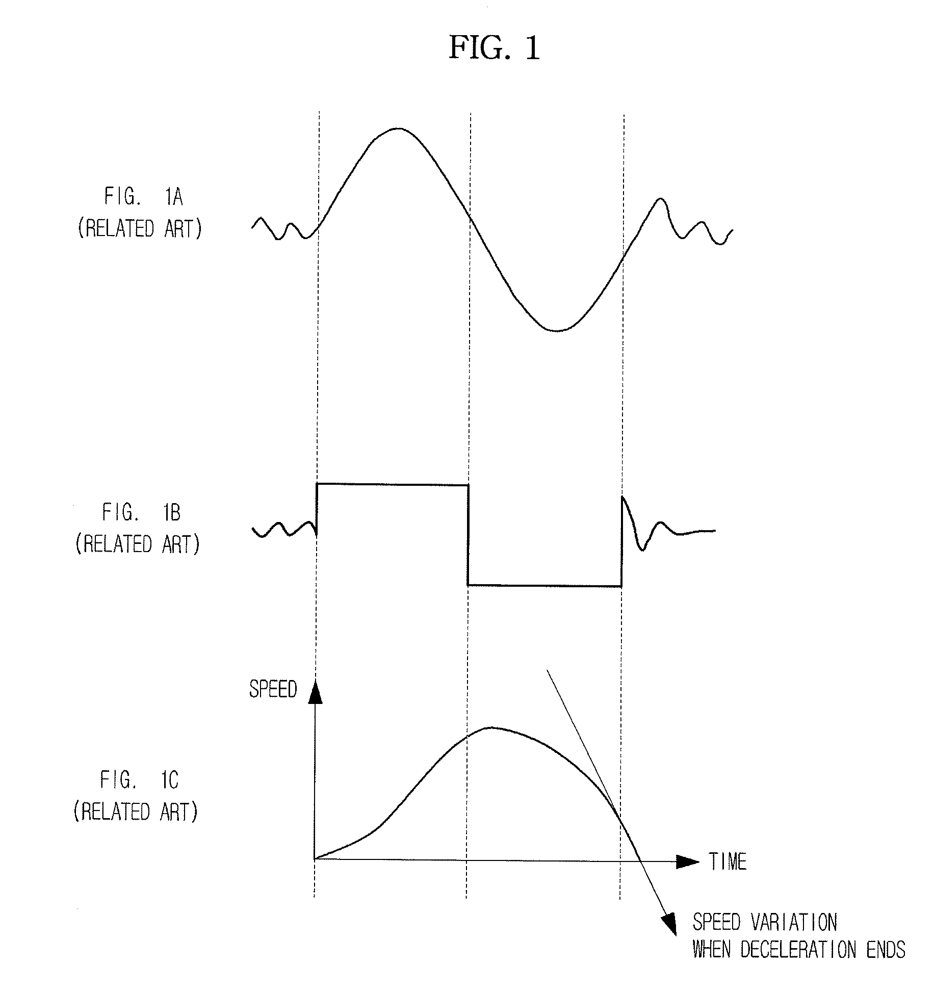
However, when the driving amount is small, a jump to a target track may fail due to a response delay of the actuator or an influence by a signal variation.
Furthermore, since the driving amount for acceleration and deceleration is small, searching an optimal driving time and an optimal driving amount is difficult.
However, when a driving amount is decreased for a low speed, since a speed variation is greatly generated as time elapses, accelerating and decelerating driving is unstable at a short time period and searching an optimal driving time and an optimal driving amount is difficult.

Method used


Image

  • Optical recording/reproducing apparatus
  • Optical recording/reproducing apparatus
  • Optical recording/reproducing apparatus

Examples


Embodiment Construction

[0040]Reference will now be made in detail to embodiments of the present general inventive concept, examples of which are illustrated in the accompanying drawings, wherein like reference numerals refer to the like elements throughout. The embodiments are described below to explain the present general inventive concept by referring to the figures.

[0041]A description will be given of an exemplary embodiment of the present general inventive concept with reference to FIGS. 2 to 4C.

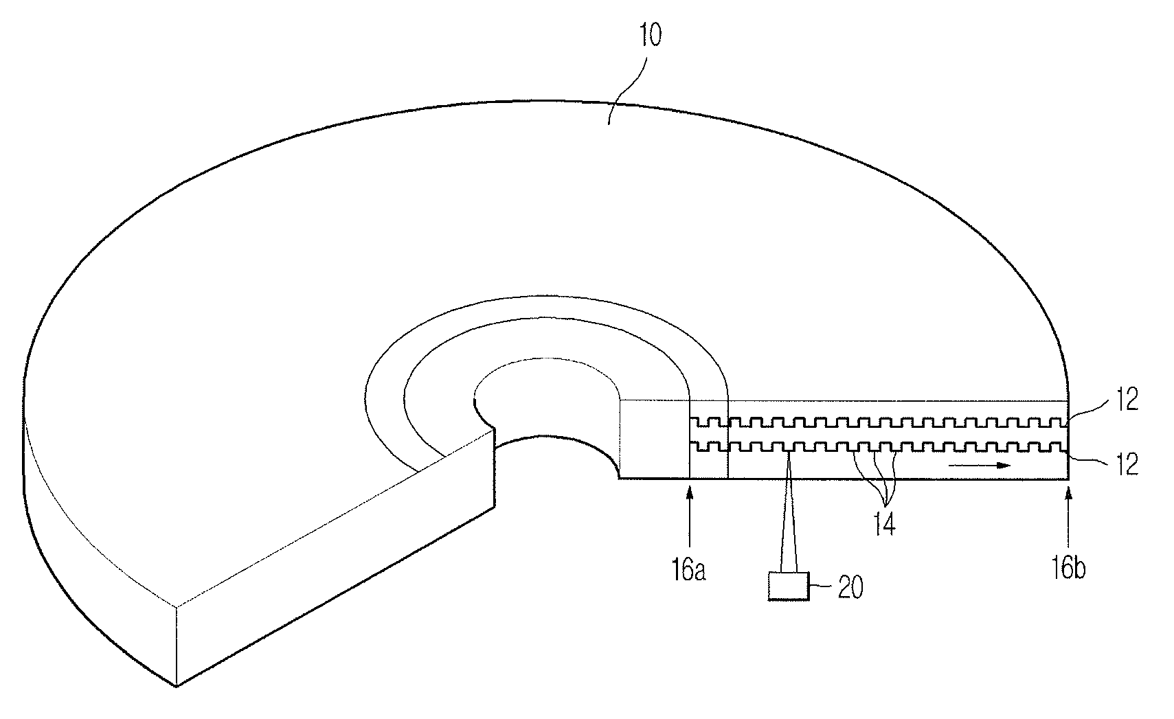
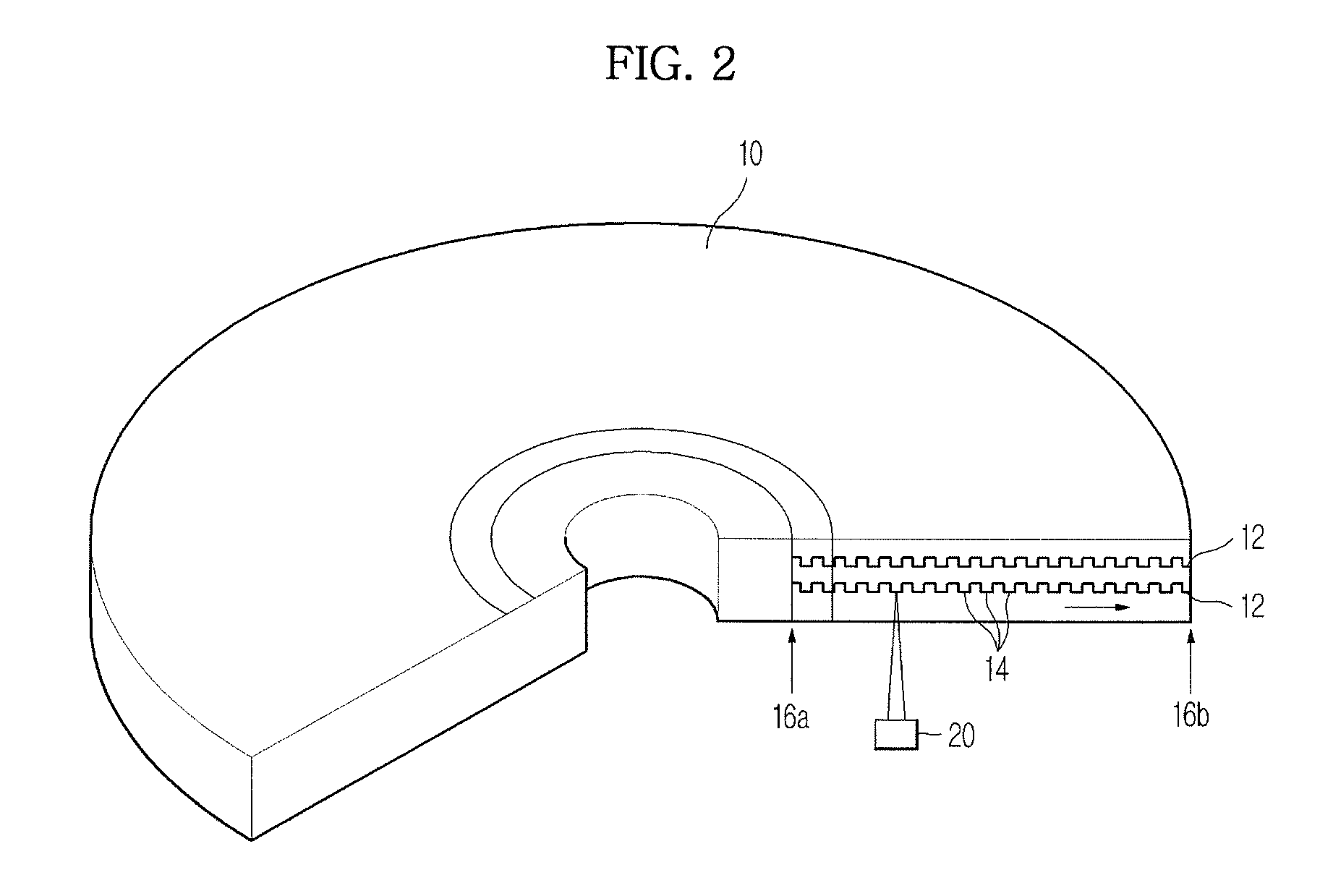
[0042]FIG. 2 is a cross sectional view illustrating an outer configuration of a disc of an optical recording / reproducing apparatus according to an exemplary embodiment of the present general inventive concept. Referring to FIG. 2, a disc 10 is a recording medium having layers 12 in which information is recorded. The disc 10 may include a low-density disc, such as a CD or a DVD, or a high-density disc, such as a BD or an HD DVD. Spiral tracks 14 are successively formed on the layers 12 of the disc 10.

[0043]In g...


PUM


Abstract

An optical recording / reproducing apparatus includes a disc, a pickup to irradiate a laser beam to the disc and detect a reflected light of the irradiated laser beam, a controller to generate a tracking error signal from a signal of the reflected light and generate a control driving signal for track following by using the tracking error signal, a driving unit to perform tracking servo control by driving an actuator of the pickup according to the control driving signal, and an output unit to output an accelerating and decelerating control driving signal transmitted to the driving unit during the tracking servo control as a pulse width modulation (PWM) signal.

Description

CROSS-REFERENCE TO RELATED APPLICATIONS[0001]This application claims priority under 35 U.S.C. §119(a) from Korean Patent Application No. 2008-0029606, filed on Mar. 31, 2008 in the Korean Intellectual Property Office, the disclosure of which is incorporated herein in its entirety by reference.BACKGROUND OF THE INVENTION[0002]1. Field of the Invention[0003]The present general inventive concept relates to an optical recording / reproducing apparatus and, more particularly, to an optical recording / reproducing apparatus which to stabilize a jump between tracks of a disc.[0004]2. Description of the Related Art[0005]With the development of video and audio media, discs capable of recording high-quality video information and high-quality audio information for a long time have commercially been used.[0006]A disc varies a reflection of a laser beam by punctuating lots of pits on a surface thereof, thereby recording and / or reproducing information such as voices, images, and documents. A low-dens...

Claims


Application Information

Patent Timeline
IPC IPC(8): G11B7/00
CPCG11B7/08523G11B2007/0013G11B7/08529G11B7/09
Inventor UTO, TOSHIKI
Owner SAMSUNG ELECTRONICS CO LTD
Learn More