Communication system

a communication system and communication technology, applied in the field of communication equipment, can solve the problems of large processing capacity of the decoder, unnecessary bandwidth expansion, and impractically bad error rate performan

Inactive Publication Date: 2009-10-01
KOKUSA ELECTRIC CO LTD
View PDF2 Cites 22 Cited by
  • Summary
  • Abstract
  • Description
  • Claims
  • Application Information

AI Technical Summary

Benefits of technology

[0039]Therefore, by using a combination of repetition code and extended mapping, it becomes possible to match the EXIT curve of the demapper and the EXIT curve of the decoder (in other words, the EXIT curves are matched closely each other and the intersecting point appears in a region near the vertical axis on the right side of the EXIT chart) in a very simple method (in other words, with avery easy to decode). Thereby, an error rate threshold can be generated.
[0049]As described above, by using combinations of repetition codes and extended mapping, the invention makes it possible to match the EXIT curve of the demapper and the EXIT curve of the decoder (in other words, the EXIT curves are not separated unnecessarily each other and the intersecting point appears in a region near the vertical axis on the right side of the EXIT chart) in a very simple method (in other words, without requiring heavy decoding complexity). Thereby, an error rate threshold can be generated.

Problems solved by technology

Therefore, there is a problem that the decoder requires a large processing capability.
When the curve intersection happens when only relatively low mutual information is achieved (i.e., when the intersection takes place at a point near the vertical axis on the left side of the EXIT chart), impractically bad error rate performance is obtained.
However, the code with a reverse S-shaped curve at a low level corresponds to a low-rate code, which means that unnecessary bandwidth expansion is required (in other words, the turbo equalization system itself is not making full use of the channel is transmission capability, or a loss of the information rate is being incurred).
In such cases, error rate “threshold” happens.
On the other hand, when the two EXIT curves are unnecessarily separated each other, the channel's capability is not fully utilized (in other words, the communication channel capacity cannot be achieved asymptotically).
However, in the cases of the turbo and the LDPC codes, the codes themselves require a large number of iterative processing within the decorder, which necessitates a large processing power.
In other words, there is a problem that a large processing complexity for decoding is required when the code is designed to fit for the gray mapping.

Method used


Image

  • Communication system
  • Communication system
  • Communication system

Examples


Embodiment Construction

[0057]Preferred embodiments of the invention will be described with reference to the drawings.

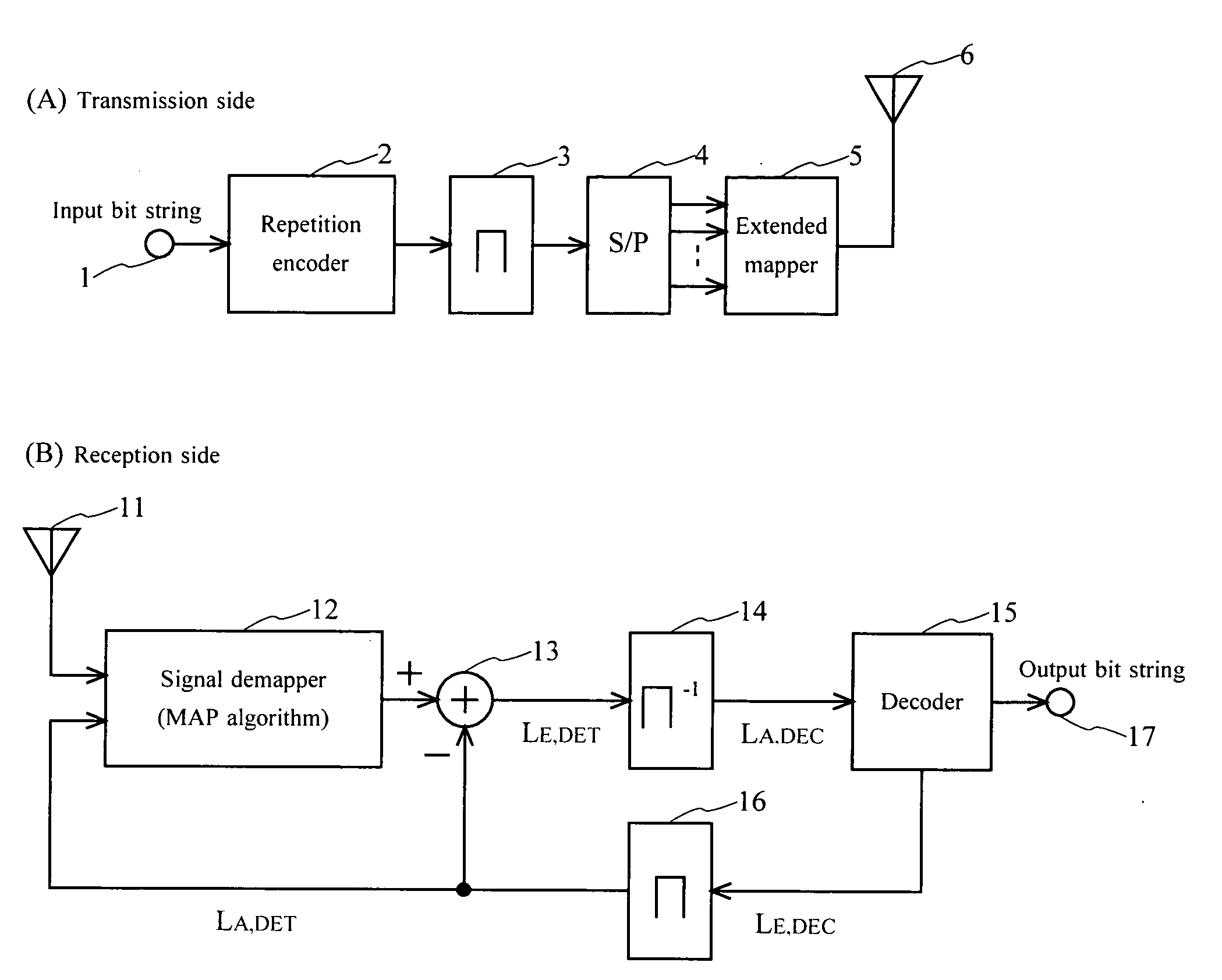
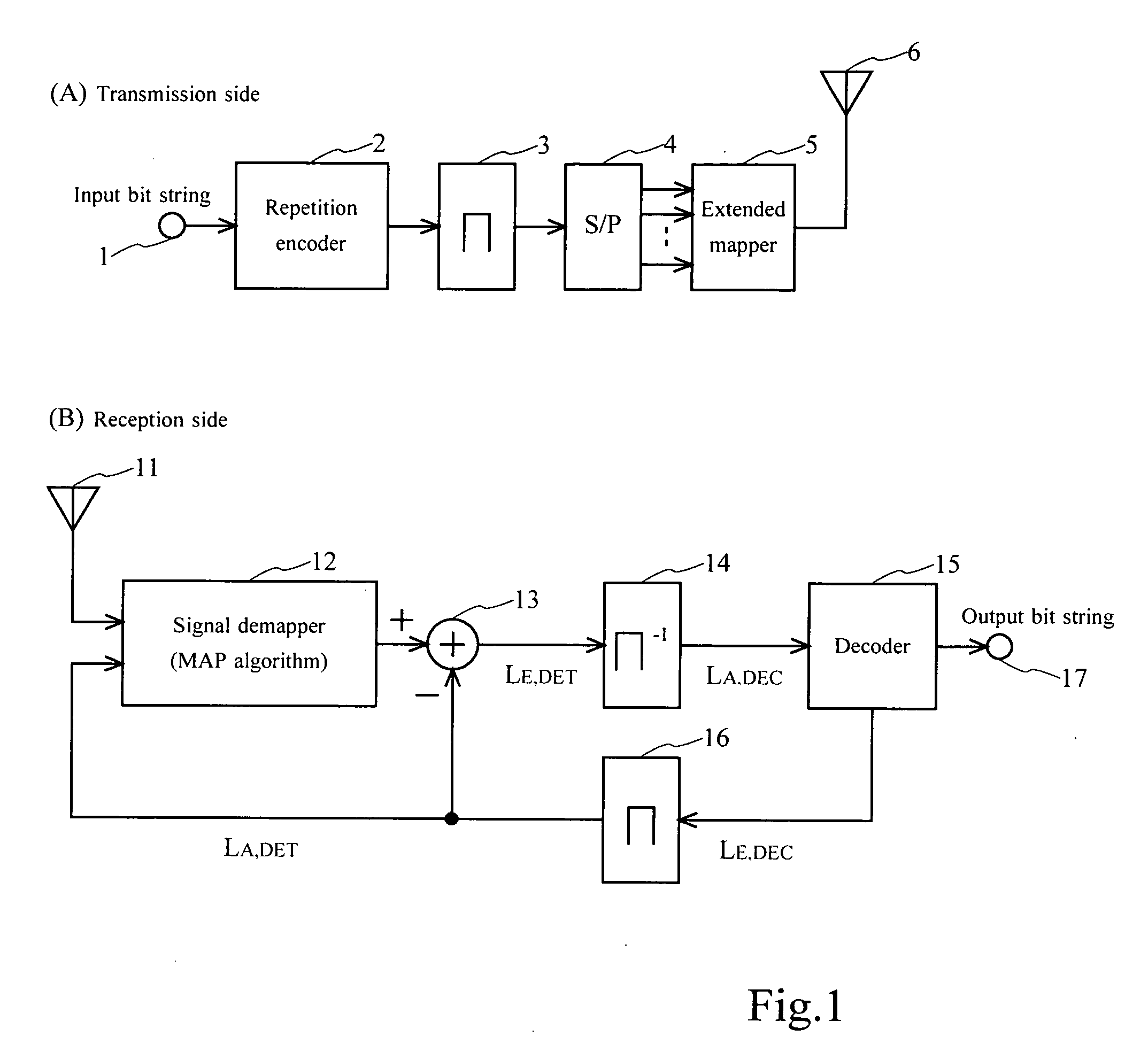
[0058]FIG. 1A shows a configuration example of a transmitter according to a possible embodiment of the invention, and FIG. 1B shows a configuration example of a receiver according to a possible embodiment of the invention.

[0059]It should be noted that although the transmitter and the receiver are illustrated separately in this example, it is possible that a communication system is comprised of both the transmit and the receive functions.

[0060]As shown in FIG. 1A, the transmitter of this example is comprised of a bit input 1, a repetition encoder 2, an interleaver 3, a serial / parallel (S / P) converter 4, an extended mapper 5, and a transmission antenna 6.

[0061]As shown in FIG. 1B, the receiver of this example is comprised of a receive antenna 11, a signal demapper (MAP algorithm) 12, an adder 13, a deinterleaver 14, a decoder 15, an interleaver 16, and a bit output 17.

[0062]Schematically, in ...


PUM


Abstract

A communication system receives a signal that is coded using a repetition encoder (2) in a transmitter side, thereafter extended-mapped by an extended mapper (5), and transmitted by a transmitter (6). A demapper (12) demaps the received signal, corresponding to the extended mapping. The decoding unit (15) decodes a result of the demapping, corresponding to the coding using the repetition code. Mutual information between the transmitter coded bits and the log likelihood ratios of the demapping and decoding results is increased by exchanging the likelihood ratio between the demapper (12) and the decoder (15).

Description

BACKGROUND OF THE INVENTION[0001]1. Field of the Invention[0002]The present invention relates to a communication apparatus, and more particularly channel coding and a mapping method to a modulation signal point in a transmission side and iterative signal processing between a demodulator and a channel decoder for signal detection at a receiver side in a system that transmits and receives digital signal using a digital modulation method through a wired or wireless channel suffering from noise.[0003]2. Description of the Related Art[0004]Various high-performance codes, such as LDPC code and RA code, have been found since the discovery of the turbo code, which approaches the communication channel capacity, in 1993. A technique that is common to these codes is that decoding is carried out by a belief propagation algorithm. Recently, there have been a number of attempts to combine the decoding based on the belief propagation algorithm and other functions necessary for communications in or...

Claims


Application Information

Patent Timeline
Patent Type & Authority Applications(United States)
IPC IPC(8): H03D1/00
CPCH04L25/03171
Inventor MATSUMOTO, TADASHIAXEL, DAUCH
Owner KOKUSA ELECTRIC CO LTD
Why Eureka
Try Eureka