Auto-calibration method for a projector-camera system

a technology of projector camera and automatic calibration, which is applied in the direction of image analysis, instruments, computing, etc., can solve the problems of traditional calibration methods such as the eight-point algorithm and the five-point algorithm failing or giving poor performance in planar or near-planar environments, and achieve the effect of improving the quality of the results

Active Publication Date: 2009-10-01
CITY UNIVERSITY OF HONG KONG
View PDF3 Cites 51 Cited by
  • Summary
  • Abstract
  • Description
  • Claims
  • Application Information

AI Technical Summary

Benefits of technology

[0010]To improve the quality of the results

Problems solved by technology

Traditional calibration methods such as the eight-point algorithm and the five-point algorithm will fail or give poor

Method used


Image

  • Auto-calibration method for a projector-camera system
  • Auto-calibration method for a projector-camera system
  • Auto-calibration method for a projector-camera system

Examples


Embodiment Construction

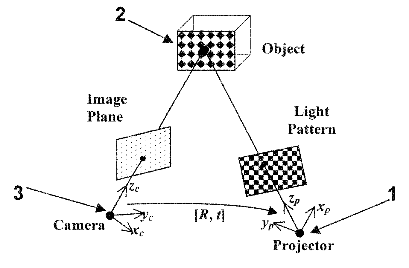
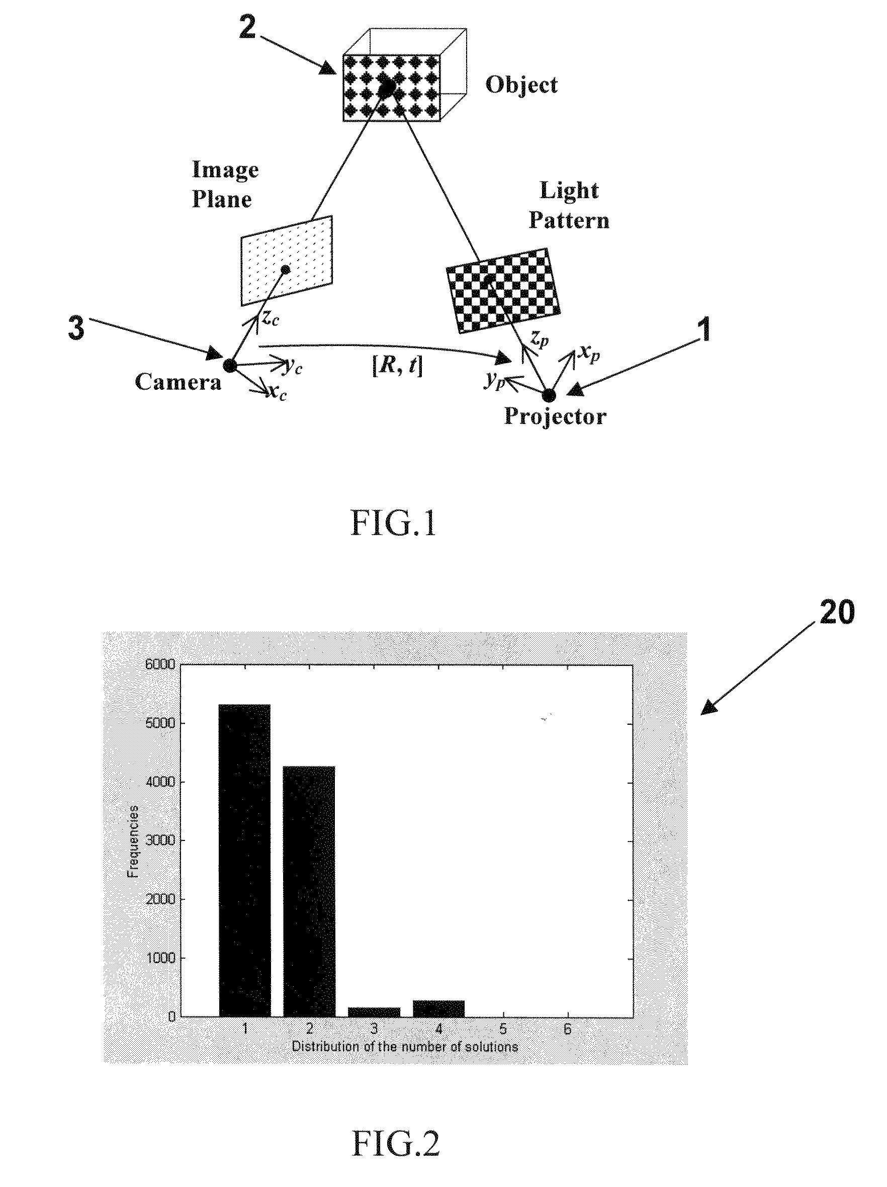
[0024]FIG. 1 shows the geometrical relationships in a structured vision system comprising a projector 1, an object 2 and a camera 3. The projector 1 is controlled by a computer and projects a light pattern onto the object. The surface of the object 2 will distort the light pattern and these distortions are captured by the camera 3 and used for calibration of the system and then reconstruction of the scene.

[0025]For the camera and projector a right-handed coordinate system is defined with the origin of the coordinate system being at the optical centers of the camera and projector respectively. Let R and t be the rotation matrix and translation vector from the camera to the projector, and the world coordinate system coincides with the camera coordinate system. The projector may be regarded as a pseudo camera and the camera is of a pinhole type. With these conditions the intrinsic parameters of the projector and camera can be given by the following matrices:

Kp=[fu′s′u0′0fv′v0′001](1)Kc...


PUM


Abstract

A method for self-recalibration of a structured light vision system including a camera and a projector. A camera plane and a projector plane are defined, a Homography matrix between the camera plane and the projector plane is computed, and a translation vector and a rotation matrix are determined from Homography-based constraints. A computer vision system implementing the method is also described.

Description

FIELD OF INVENTION[0001]This invention relates to a method for the automatic calibration of a vision system such as a projector and a camera, and in particular to a method for the self-calibration of a structured light system via plane-based homography. The invention also relates to a computer vision system that uses such a method.BACKGROUND OF THE INVENTION[0002]Camera calibration and 3D reconstruction have been studied for many years but is still an active research topic that arises in the fields of object modeling, mobile robot navigation and localization, and environment building amongst others. In all these applications there is a need to obtain 3D information of an object or scene from a 2D camera image.[0003]In general, the problem of camera calibration and 3D reconstruction can be approached in three different ways. When both the intrinsic and extrinsic parameters of a vision system are known, the 3D reconstruction can easily be obtained by traditional triangulation methods....

Claims


Application Information

Patent Timeline
IPC IPC(8): G06K9/36
CPCG06T7/0018G06T7/80
Inventor LI, YOUFUZHANG, BEIWEI
Owner CITY UNIVERSITY OF HONG KONG
Why Eureka
Try Eureka